What's new
What's new

CHMF IN insanity (M32 control)

SMT

Hot Rolled
Joined
Dec 9, 2010
Location
PA
These chamfering processes are driving me nuts!

I have a small 3/16 chamfer cutter (45*) that I have described as a chamfer cutter with a .19 diameter.

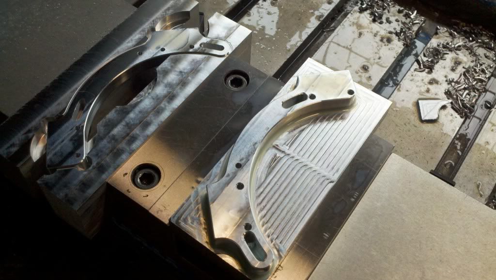
Im doing 2 ops to an aluminum part in the vise and want to chamfer the outside profile and some slots that go through the part.

On side one-

For the profile Chmf OUT works perfectly! Sweet!
For the slots (for bolts im sure) I used CHMF LEFT and while it did run, it overcut a the start point. Almost like it was on the wrong side of the line before it started the comp move.

Side two
For the profile, CHMF OUT works perfectly! Sweet!
For the slots, i can't get it to run at all. I get an illegal radius alarm with both IN and LEFT processes.

I took all my numbers from a cad drawing. I flipped the drawing over and moved the zero point and took all my new dimensions (for side 2) from the new zero. I have double and triple checked my cad numbers as well as what I typed into mazatrol and the numbers all match up.

WTF?!?!

Any ideas?
 
2012-11-20_11-50-06_788.jpg


Been talking to Mazak apps. We got the first side over cutting fixed by changing CHMF LFT to CHMF IN.

Side two has been troublesome. I sent him my cad drawing and he opened it in mastercam and got locations to 5 decimal places, programmed it on a machine and it ran. M32 only goes to 4 places so back to the drawing board.

I took a closer look at my drawing and it seems some of my points were incorrect. So, I fixed that and typed in the new numbers and pretty much have the same problem. I use the "check" button after each entry to see where things go wrong and will make 3 of the 4 arcs but the end point of the third one I think is wrong (which is why it can't connect to the end point of the 4th arc with the radius I specify.

What gets me is the cad drawing visually looks like I want. What shows up in Mazatrol graphics isn't even close, yet both systems are using the same points!
 
Forgot to add that Im only working on the left slot on the left part in the pic for starters. . .
 
although i generally only have trouble with chamfer cycles cause the control thinks it doesnt have room to use the cutter i picked my workaround is to just call it an endmill and do a line in or line left.

on the "wrong side" problem make sure you reset your starting points anytime you change something in that unit. I have also had problems when changing actual cutter diameter on some parts cause the new start point is on the other side of the part on a line out so it goes to the old point and then cuts clear through the part to get to the new point.
 
Side two has been troublesome. I sent him my cad drawing and he opened it in mastercam and got locations to 5 decimal places, programmed it on a machine and it ran. M32 only goes to 4 places so back to the drawing board.

Sounds like a rounding error if you are inputting the points manually in a Mazatrol program. I get the same issues on the lathe when I input a spline.

Change the endpoint by of the small arc by closing the gap by a tenth on each end or perhaps, increase the full R radius value at the end of the slot by 2 tenths or more. My guess is the full R at the end of the slot is curving back on itself by 50 millionths and your control does not like it.

I was wondering about that somewhat. The parameter that governs this is set to .0002" and I haven't changed it yet.

Another interesting note- I programmed the right side slot and it came out perfect.

I also added drilled hole locations at each of the tangent points of the 4 arcs so I had something of a visual reference to look at on the graphics screen. The arcs didn't meet up with the drilled hole locations at all, despite them being the same numbers in both processes! WTF is going on?

I'm stumped and I have the guys at Mazak stumped. He put my numbers into a matrix control and it runs fine. He sent me a printout of his program, I put in his numbers (slight change in tool path) and while it was able to run through graphics, the shape was wrong (distorted on one end for some reason) When I hit cycle start I got a tool trespass alarm (which was new) A screen shot from his end shows exactly the shape i drew up in CAD. . .
 
Another interesting note- I programmed the right side slot and it came out perfect.

The rounding errors from a CAD system can either work in your favor (ie, they go unnoticed because it worked), or they work against you even for the same part from the same file. This leaves you confused because you did the same exact thing--type in the numbers from CAD--and sometimes it works and sometimes it does not. When it does not work, it's usually from two radii trying to blend in a perfect tangent, of which the intersect position is RARELY a perfect 4 digit number.

Again, move the rounding error to the other side of 'perfect' by manually fudging the numbers by a few tenths when you type them into the program so the controller is happy and you make parts.

Another way around the rounding error is to let the Mazatrol calculate it's own intersect positions. Draw up the curved slot but leave the ends squared off in relation to the slot. Add a fillet radius in the geometry so the machine smooths out the square slot to a full radius and recheck. Doing it this way works better on a lot of stuff (lathe and mill) by avoiding the CAD rounding error.
 
Check U49, it's the circle end position allowable error amount. My bet is it's set to the factory 10 microns. I've changed all of our machines to 50 microns.
 
Well, I got it solved. Sort of.

We discovered that one slot (the one that ran ok) was actually slightly longer than the one that didn't run. I ended up rotating the good slot around to replace the bad one and put those numbers in and it worked fine.

Thanks for all the input. I'll check U49 tomorrow. Good call.


Back
Top