What's new
What's new

Integrex contactor problem

integrex123

Plastic
Joined
Aug 27, 2018
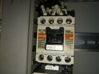
I have a problem main spindle coolant radiator fan contactor. I measured control current A2 and it looks like the fault is there. What does the control current come from? Is it possible to take control directly from somewhere else?

Integrex 200 sy 2002

cnc contactor - YouTube
IMG_20180814_150147.jpg

IMG_20180107_132705.jpg

IMG_20180814_150121.jpg
 
I have a problem main spindle coolant radiator fan contactor. I measured control current A2 and it looks like the fault is there. What does the control current come from?

Although it's possible that a controller output is going bad, it is highly unlikely. The problem is most likely a dirty set of NC auxiliary contacts on the thermal overload F12. Power from the controller first passes through these contacts before going to the contactor coil. These contacts often fail, as they rarely, if ever get exposed to make/break cycles that keep them clean.
 
I have a problem main spindle coolant radiator fan contactor. I measured control current A2 and it looks like the fault is there. What does the control current come from? Is it possible to take control directly from somewhere else?

Integrex 200 sy 2002

cnc contactor - YouTube
View attachment 236671

View attachment 236672

View attachment 236673


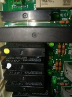
before you start improvising. Go to page SECTION 4/ 401810. Find what energizes KM 12. That is going to be either PCB board or IO Remote board. Depends on age it will have either SSR relay , normal relay or thyristor. Lots of time this element will be faulty, you can take one ( if there is available ) from other output and re-solder it.

the idea is next. PLC out put energizes SSR or transistor, then this SSR or transistor energize KM12, then this KM12 provides feedback back to PLC that it was energized and thermal trip is not triggered.

And, if you going to connect it to another SSR relay to get control voltage, make sure you do not overload this SSR or Transistor with extra current. 99% dead electronics comes from the fact that the heat was not properly evacuated from this electrical component. Easy.


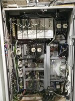
P.S. see that board covered with transparent plastic at the very bottom of cabinet? That is where this SSR is sitting.
 
Thanks to all the respondents. I measured the line that goes to the thermal relay F12 (503 -> 95) and the power is disconnected from it. I changed the SSR relay but it still does not work. Any ideas?


IMG_20180906_130625.jpg

IMG_20180907_172918.jpg

IMG_20180918_195044.jpg
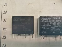
The original ssr relay omron g3mb-102PL-UTU could not be found at all but the local Electricity store said it has been replaced by omron g3mc-202pl-vd.
 
Thanks to all the respondents. I measured the line that goes to the thermal relay F12 (503 -> 95) and the power is disconnected from it. I changed the SSR relay but it still does not work. Any ideas?


View attachment 238415

View attachment 238416

View attachment 238417
The original ssr relay omron g3mb-102PL-UTU could not be found at all but the local Electricity store said it has been replaced by omron g3mc-202pl-vd.

yes. you can replace with this type of ssr. What about LED that is indicating +24 DC when PLC is energazing SSR? Is it on or off? Is SSR getting +24 DC?

Try to move jumper on XB4 , put it on pins 2 and 3, to isolate PLC. Then you must get permanent +24DC to energize SSR, in case PCB tracks are not damaged
 
All other LEDs are on except HL102 which is just next to the ssr relay. Does this mean that ssr relay does not get + dc24? I tried to move the jumper XB4 but there was no difference.

Probably this problem could be repaired easily by switching the whole AP1 circuit board but I believe that I can run the machine normally even if the cooling fan is not energized ...

I marked the SSR relay and jumper with the red point
puolijohde rele1.jpg
 
wait a minute. According to your drawing it works like that:

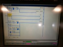
-PLC output Y9 must be zero to energize SSR. ( you can check if it zero on ladder diagram screen, searching for -( )- Y9 device.


-then there two inverters on PCB board, one will make the signal positive level, next -negative level again.
It is very bizarre configuration to be honest

-Then by means XB8 SSR gets +24 DC and by means XB4 it gets zero volt.

-if PIN2 XB8 has +24 DC and PIN2 XB4 has zero volts, SSR must stay open.

P.S. something isnt right with you moving XB4 jumper, if you move it (connect pins 2 and 3 ) and XB8 (connect pins 1 and 2)....... you will bypass PLC Y9 output and just energize SSR permanently, which is not a bad idea at all.
 
very simple. you go to VERSION, you press most right button below the screen, then you type 1131 and INPUT.
I am not even sure you must use 1131 mode, it can be available with entering this number.

Then somewhere on DIAGNOSTIC page you see LADDER. You press it, once you are inside you press MONITOR and select type of DEVICE you need to look at, then you type name of the device and INPUT. Then you press input few times until you see what you are looking for.
 
something is very strange with this Y9 PLC outout, I checked ladder diagram, and it doesnt really exist on INTEGREX Mk1 , like it is connected but there is no PLC output associated with Y9. Sort of, this Y9 output must stay always OFF to be able to energize SSR. At this point I see it is much better to bypass with jumpers, the way I mentioned before.
 
Have not had time to find out this problem but today I look at it a little bit again.

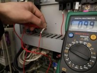
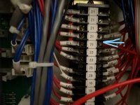
I put the direct current on the contactor with the xt1 terminal block and the fault is fixed and everything works correctly. But now that when you supply power from other sources then the current also comes from the ssr relay (503 wire), but if you put the 503 wire on the back of the contactor then it will not be powered at all, mysterious ..


picture of where I got the power to the contactor
InkedIMG_20181202_145237_LI.jpg
picture where contactor works, power supply xt1 21 wire
IMG_20181202_145441.jpg
picture shows that now also the original 503 cable is powered
IMG_20181202_145517.jpg

any ideas?
 
Have not had time to find out this problem but today I look at it a little bit again.

I put the direct current on the contactor with the xt1 terminal block and the fault is fixed and everything works correctly. But now that when you supply power from other sources then the current also comes from the ssr relay (503 wire), but if you put the 503 wire on the back of the contactor then it will not be powered at all, mysterious ..


picture of where I got the power to the contactor
View attachment 243558
picture where contactor works, power supply xt1 21 wire
View attachment 243557
picture shows that now also the original 503 cable is powered
View attachment 243559

any ideas?


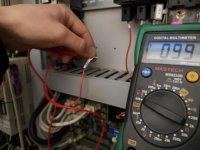
your multi-meter is device that sense DC voltage drop across internal to FLUKE resistor. Lots of time a static voltage or capacitor leakage voltage will tell FLUKE that there is AC or DC voltage available
to energize a relay...but... in reality , this voltage has no current ( no power) and multimeter is offseted on its AC or DC inputs by nano ampers.. .whereas to energize relay you need milliampers. So, the take away message..always measure voltage or current in your particular situation under the load.

People who makes FLUKES tries to make them superior and be able to measure everything, and at the end of the day...you starting to measure noise. Very good FLUKES , specially oscilloscopes, can make themselves dumb, with the function SMOOTH, where digital channel becomes dumb. What I think is best and every best achievement of FLUKE company as it is. Have their multimeter and oscilloscope, cant complain.
 
Yeah, this might explain this mystery. So I take power on xt1 21 wire and the problem is resolved. Thanks for the answers.


Back
Top