How to install the app on iOS
Follow along with the video below to see how to install our site as a web app on your home screen.
Note: This feature may not be available in some browsers.
You are using an out of date browser. It may not display this or other websites correctly.
You should upgrade or use an alternative browser.
You should upgrade or use an alternative browser.
Mazak qt15n spindle doesn't spin
- Thread starter Yatarra
- Start date
- Replies 9
- Views 2,811
benganboll
Hot Rolled
- Joined
- Feb 23, 2015
- Location
- Sweden Östersund
I guess its a T32 and then spindle load is normal when turning spindle by hand.
Is this machine new to you or when did it work as normal?
What happens if you press the jog button?
Is this machine new to you or when did it work as normal?
What happens if you press the jog button?
cnctoolcat
Diamond
- Joined
- Sep 18, 2006
- Location
- Abingdon, VA
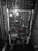
Most likely your FR-SF spindle drive is bad.
And the most common failure point on the FR-SF is the DC power supply --- the large black box at the top.
Also look close for signs of damage on the main circuit board, and the IGBT's underneath the main board.
Also, replacing all the electrolytic capacitors is standard practice in rebuilding power supplies.
ToolCat
benganboll
Hot Rolled
- Joined
- Feb 23, 2015
- Location
- Sweden Östersund
I have never seen a spindle drive broken without any alarm.
What happens when you try to start spindle in these conditions:
1, in auto mode with a program
2, by manual
3, by pressing the jog button
Could it be a parameter problem, like if max rpm is set to 0.
What happens when you try to start spindle in these conditions:
1, in auto mode with a program
2, by manual
3, by pressing the jog button
Could it be a parameter problem, like if max rpm is set to 0.
Actually, it was in repair and I thought the problem was somewhere else in the machine. Is there any way to check if the inverter is good? Should I advertise repair right now?
Yes, its t32-2
Power supply looks good, there is green led on it.
So it was sent out, very interesting.
If the sequence order was changed and not returned back to its original setting while sent out this scenario could happen and did happen to me.
Check for proper firing order in simple words. Example #1 #2 #3 #4 #5
On the back of each drive is a finger nail lid or cover, open each lid.
On each drive note what number each is set to. If you have two drives set to the same firing order that is wrong.
Example, #1 #2 #3 #3 #4 #5.
See there are two #3, that is bad.
No alarms will show also.
Note the red LED on the SF-TL card. According to the instructions the inverter means "Encoder circuit breakage detection".
I set the parameters of the inverter myself, when it came back from repair. (parameters were added to the machine during the purchase, I hope they are good).
Mr.e, could You explain how to check this sequence more accurately? I dont know how to start. Maybe there is a problem here.
I would be grateful
Regards,
Sebastian
You mentioned that you sent out the drive to be checked out, very good.
I'm just saying while it was being diagnosed a setting wasn't put back before returning back to you.
On the drive is a red led only displaying 2 characters like A7 for example. Right next to this led is the lid I spoke of.
Simply open the lid and note or wright it on the drive itself.
Do the same for all the drives that have lids right next to the red led.
When your all done no two numbers should be the same.
If you do have two numbers the same your 2nd spindle will not work and you will have no alarm.
I experienced your exact scenario when the drives were swapped out with another drive sharing the same number setting.
This is just something that should be checked.


