What's new
What's new

Mazatrol M32a Trouble

MARIOMUNDACA

Plastic
Joined
Aug 20, 2018
Hello

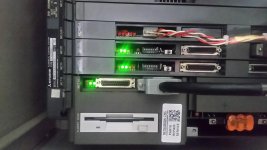
We have a Mazak YMS-30 machining center with the following problems.

- There is no signal to the screen, it is on but black.
- Some alarm LEDs are registered in the numerical control module and in the MC221A board of the Mazatrol M-32 panel
- I detail states of leds:

MC712:
- LED 1: Off
- LED 2: Off
- LED 3: Blinking
MC161-1
- LED1: On
- LED2: On
- LED3: On
- WDOG: Off
- D.AL: On
- D.WD: On
MC126
- LED1: On
- LED2: On
- LED3: On
- WDOG: On
MC446
- LED1: Off
- LED2: Off
- LED3: On
- LED4: there is no
- LED5: Off
MC221
- RD: On
- SD: Off
- MON: Blink

The procedure to reinitialize the Ram has already been tried, but without obtaining results.
The LED 3 of the MC446 card is still on, according to the manual it is due to the battery failure, the 3.6V and 6V battery has been changed with new ones, but the status of the LED does not change, it still indicates an error.
How can I verify if the MC446 or MC062 card is defective? Can it be possible that other cards are wrong?
 
MC161-1
- LED1: On
- LED2: On
- LED3: On
- WDOG: Off
- D.AL: On
- D.WD: On

MC161 can be a problem, D,AL and D.WD is DSP part of MC161 is not working. Does the MC161 have an extra small board attached to it?
The only way to test it is to take similar board from similar machine and swap them.
 
I have been on the road for the last week, just got in.
I am responding to your PM here.

Look at the operator panel below the screen, there should be some LED's there too.

Have you checked the power supply voltages?

It has been long enough since I worked on a machine with this control I don't remember what board # is what board.

If you post good pictures of the inside of the operator panel and pictures of the CNC chassis so I can read the MC #,
I may be able to help.

Bill
 
IMG_20180810_102327.jpg

Hi.
On the operator panel is the MC221A card, the state of the LEDs is RD: On, SD: Off and MON: Blink.
The voltage that power the card are -11.6V, 12.2V and 5.2V.

Thanks.

Mario Mundaca.
Mail: [email protected]
Wapp: +51992408989
 
View attachment 236829

Hi.
On the operator panel is the MC221A card, the state of the LEDs is RD: On, SD: Off and MON: Blink.
The voltage that power the card are -11.6V, 12.2V and 5.2V.

Thanks.

Mario Mundaca.
Mail: [email protected]
Wapp: +51992408989


this board. RD WR, MON , just show you that there is data exchange happening in between NC, keyboard and monitor. No need to look here until NC errors are clear.
 
the problem is either MC161-1 or memory MC 446. I have seen MC446 with 3 rd LED ON, despite the fact that batteries were good, they were working alright. The only way is to swap them with another boards. I bet Mitsubishi can connect Laptop to MC161-1 and go into debugging mode, and download memory damp to see what is faulty... but I never seen anybody doing this.
 
A missing instruction in all of these initialize instructions is the need to have the program lock switch in the enable position to successfully initialize the control.
 

Attachments

  • 20180830_145323.jpg
    20180830_145323.jpg
    88.6 KB · Views: 184
Lights on the boards for a running system.
Note: They are all green, any missing green denote a problem, as any red also mean a problem.
The first pic is of the MC-221 board.
The left LED blinks slower than the other 2 that blink faster.

The second picture is of the MC-712
The top blinks faster than the one below.

Next comes the MC-111
Both green blink at a medium speed.

Next is the MC-121
Both green are on.

The third photo shows the last boards, MC-303, MC-301 and the PS-21 each have one green LED that is on.

The 4th photo is the floppy that is left in the drive shown in the second picture.

The last photo is the front panel.

Bill
 

Attachments

  • 20180830_142415.jpg
    20180830_142415.jpg
    104.5 KB · Views: 148
  • 20180830_142618.jpg
    20180830_142618.jpg
    89 KB · Views: 318
  • 20180830_142653.jpg
    20180830_142653.jpg
    84.5 KB · Views: 184
  • 20180830_142901.jpg
    20180830_142901.jpg
    83 KB · Views: 240
  • 20180830_145313.jpg
    20180830_145313.jpg
    90.3 KB · Views: 179
The picture I posted above are from an early M-32 A control.
Your control uses a newer board set but they are similar to the ones in the photos.

I suspect that the initialize did not complete properly, or the parameters did not load properly. And Yes you may have one or more bad boards.

Have you checked the power supply voltages at the test points below the LED?

Bill
 
A missing instruction in all of these initialize instructions is the need to have the program lock switch in the enable position to successfully initialize the control.


To do the process of memory reinitialization it is necessary to change the state of the switch to enabled?
 
The picture I posted above are from an early M-32 A control.
Your control uses a newer board set but they are similar to the ones in the photos.

I suspect that the initialize did not complete properly, or the parameters did not load properly. And Yes you may have one or more bad boards.

Have you checked the power supply voltages at the test points below the LED?

Bill

Yes, the power supply voltages are ok


Back
Top