Isak Andersson
Aluminum
- Joined
- Nov 3, 2021
Hello. I'm getting some weird results when I try to simulate my program. It looks like it's cutting a taper in the X direction but only in BAR OUT. All other operations look fine. It does look straight in SHAPE CHECK but not in TOOL PATH or VIRTUAL MACHIN. What could possibly be the explanation for this?


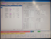
Here's the program:

It also makes some funky-looking chamfers on the ID. The 0.2 chamfer is not at 45 degrees and it adds chamfers on the inside of the corners which I don't want. What's going on there?

Here's the program:
It also makes some funky-looking chamfers on the ID. The 0.2 chamfer is not at 45 degrees and it adds chamfers on the inside of the corners which I don't want. What's going on there?