What's new
What's new

QT15 spindle motor pulley

JohnXKennedy

Plastic
Joined
Jun 6, 2017
Hey everyone - I'm in the middle of attempting to replace the (very) worn out bearings in the spindle motor of a '89 QT15. Next step is to remove the pulley from the motor shaft and I'm struggling.

I found one setscrew where the keyway is but haven't identified any others. I'm using a puller to try to separate the pulley, I've also tried heat to loosen it up to no avail.

Anyone have experience with this? Any tips (ie you missed a setscrew)?

Thanks!
 
Make sure there's not another setscrew under the one you've already removed.

Those pulleys are a tight fight. Put more heat on it, should be able to pull it off with a good puller.

ToolCat
 
Thanks for the reply ToolCat. For context the motor started rumbling badly so I pulled it to swap the bearings. I removed the back side bearing / sensor and position ring etc it all went relatively smoothly, the rear bearing was totally destroyed when I got to it. The motor now spins much better, but while its out I would like to swap the front side bearing, I'm somewhat afraid it was damaged when the backside bearing let go. Still can't get this pulley off.

I've tried heating the pulley till it smokes (used acetylene) I've tried using a large 3 jaw puller and a harmonic balancer puller that threaded into the M8 holes on the face of the pulley. I have put what seems like unreasonable force into the 3 jaw puller with a cheater bar, with heat, no dice. I soaked it in lubricant just now so maybe I'll come back to it and give it another go later, but its very stuck. It really feels like I'm missing some mechanical fastening like a screw or pin.

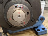
mazak1_LI.jpg

Mazak2.jpg


In these images you can see the location of the set screw I removed (image one). I could not find another screw for the life of me. Image two shows the following pulley features:
1. Balance hole opposite keyway
2. M8 puller hole
3. M8 puller hole
4. additional balance hole I assume
5. Keyway location
6. face of motor shaft, visibly mushed due to many attempts to remove the pulley with the three jaw puller

Am I missing something? The only thing left I can think to do is either keep cycling cool / hot with oil OR remove the whole motor shaft and rotor and put it on under a hydraulic press to shove the shaft out of the pulley, but that would be a huge pain.
 

Attachments

  • IMG_20200704_223939.jpg
    IMG_20200704_223939.jpg
    95.4 KB · Views: 305
Are you sure there is no set-screw down between the pulley v’s?

It seems the Japanese fastidiousness with press-fits has shown it’s ugly self!

I replaced the rear bearing on the same spindle motor a couple years back, did not do the front, and the motor has been running quiet ever since.

Maybe just replace the rear bearing and call it good?

If you do remove the entire rotor, use thin sheet plastic between the rotor and stator to prevent damage to the motor windings while pulling and re-installing the rotor.

ToolCat
 
JohnXKennedy- no way You will get that pulley with that small three-jaw puller that I see in Your picture. :O The one I used was nearly 2/3 the size of the motor.And even that with the help of pipe to increase momentum. As ToolCat said- japanese press-fit at its ugliest form.
 
The puller in that photo was the first attempt, I moved on to a larger 3 jaw but it sounds like I didn't go big enough! I'll give it one more shot but after that it's going back into the machine as is...
 
OK - I did finally get the pulley off, replace the front bearing, get it all back together and back into the machine. I'm just now finally getting around to following up on this thread.

The whole process (for anyone who attempts this in the future) is actually fairly challenging. The back bearing is easy and can be swapped using the tips in GuntisK's previous post on the subject ( to summarize - use a 0.5mm shim to space the sensor from the timing ring ). The front bearing is a real bear due to the high interference press fit of the pulley on to the motor shaft.

I finally resorted to using a harbor freight hydraulic ram puller which I mounted to the pulley with a bar of scrap material that I drilled on the mill to fit the m8 tapped holes in the pulley - but let the nose of the ram press on the motor shaft. Once the pulley was off swapping the bearing was easy.
The harder part was reinstalling the bearing. After some struggling I finally made additional adapters out of scrap material to bolt to the M10 case holes on the corners of the pulley side of the motor that let me grab onto the hydraulic ram. I then coated the shaft in engine assembly lube and put the pulley in the oven on max temp till it was good and soaked. Finally I put the pulley on the shaft and used the hydraulic ram to crank it on as fast as possible.

Everything else is just reverse of the disassembly from the machine, so far so good and I'm back to making parts! As a plus the machine now turns above 3K smoothly which it struggled to do before - just beware this is not easy to do without the ability to fabricate some puller adapters...


Back
Top