What's new
What's new

Quick Turn Smart turret/base alignment

Panza

Stainless
Joined
Oct 23, 2005
Location
Lillehammer, Norway
Machine: Quick turn smart 200M.
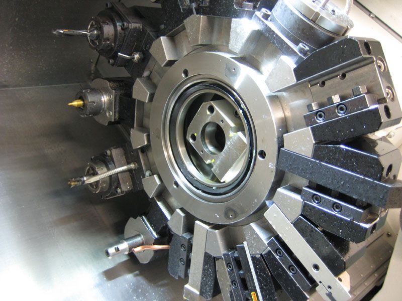
Well, I heard everyone crashes their lathe sooner or later and on the last job it was my turn: It was a really stupid mistake (maybe all crashes are stupid ?). I was aligning the tailstock and after doing that I left the chuck on the back of the tailstock. The first move in the program is a rapid down to about X = 2". I had the rapids at either 10% or 25% when the turret base hit the wrench. No damage to the tailstock it seems, since that is still in alignment, but the turret is out in the Y direction (I don't have Y-axis) about 0.020".
So the question is: What is out of whack and how do I fix it ?
I took off the cover of the turret, but the turret itself didn't hit anything so I guess that is not the place to start.

Turret-02.jpg
 
by -y- do you mean height?
if so it's probly radial location of turret.
if not I am not sure what you mean.
 
It is out in the axis perpendicular to both X & Z, so up and forward. Leaves a nub when facing.
I have looked at it a bit, also looked at the drawings, but I can't figure out where or how the turret base has moved. (Is the hollow block on which the turret swivels the turret base, or is that still just called the turret ?).
 
Can you scan that drawing for us? You need to re-align the curvic coupling. It's either right under the turret or it's on the back side of the turret. I don't know on that machine.
 
Well the live tools sure makes that a bitch of a job...

Looks to me like it works like an Integrex. 62/63 and 56/57 are the curvic. One is fixed, the other rotates with the turret. 69 is like a piston that clamps the two halves of the curvic together. Most likely pins 64 are bent.

You would have to pull that thing all the way apart and replace the pins. There might be a set of bolts that allow some adjustment without changing pins but I can't tell from the drawing.

This is not a simple job. That's probably a 1-2 day job for someone who knows what they are doing. I'd replace all the o-rings on the pistons while you are at it.

If there are bolts in the curvic that can be adjusted without a complete tear down then it's not so bad.

This video shows how it works starting at 45 seconds.
 
I sweeped inside the taper of a live holder now and the center of it is 0,4mm above the center of the spindle. The center in the X direction is 0,2mm too far back.
I sweeped along the inside of a normal toolholder while moving the X-axis and it moved 0,07mm along the length of 75mm.
Then I checked parallelism of Z-axis and tailstock. They vary 0,01mm along the length of the bed (550mm move).
The bolts that holds the turret base to the the trucks of the linear ways in X are all tight. But I guess the turret could have moved on the trucks anyway ?
I called Mazak too and their only idea was that the trucks-bolts broke or the linear ways moved.
 
Your x centerline is going to move after a wreck. I cant remember on a smart off top of head but there should be a set of bolts that are partially blocked by the mill motor. Those are the ones to loosen to realign coupling.

Take bolts out of mill motor and rotate it so you can get the blocked bolts.

Move x axis to find center in x. Tap turret which ever way it needs to go. Recheck x. Repeat till you are happy with reading. Then tighten bolts.
 
I think I got it close enough. Indicator sag really comes into play though. The bolts for the turret were on the front of the turret, underneath a cover, thin ring, and a thick ring that holds a big O-ring. Then thy are really deep. Had to make an custom allenkey to reach 138mm in there.
Measuring to the best of my ability I think the imaginary Y axis is within 0,06mm now. Is that good enough ?
Is there a variable in the control to adjust the distance from the X-axis zero to the center of the chuck ? I looked in the books but could not find it. It is off somewhere between 0,03 and 0,07mm. It would be nice to have the X-value of U-drills and live tool be an even number.
 
Measuring to the best of my ability I think the imaginary Y axis is within 0,06mm now. Is that good enough ?


Is there a variable in the control to adjust the distance from the X-axis zero to the center of the chuck ? I looked in the books but could not find it. It is off somewhere between 0,03 and 0,07mm. It would be nice to have the X-value of U-drills and live tool be an even number.

That should be fine on the alignment.

The X adjustment is your tool offset...


Back
Top