Folks,
This is for people who get a 'axis error' message on a Brown
and Sharpe MicroVal machine. I'm posting this for the next
person who has to deal with this - my problem is solved but
reply if you want to ask questions or discuss it. Also, if
anyone knows how to set the dip switches on the controller
board for one of these cmm's, I'm interested.
Mark
----
Adjusting Brown & Sharpe MicroVal CMM Axis Quadrature Signal
11/25/09 - m. mcdade
Each 9-pin axis plug contains a small circuit board with
four pots for adjusting the quadrature signal waveforms.
I did not trace out and understand the exact function of
the circuitry supporting the sensors but at the time of
this work, both the x and y axes functioned well while
the z axis produced a 'axis error' message. Cleaning and
resetting the sensors on the scales helped (several years
ago, cleaning completely eliminated an error on the y axis)
but, eventually, the z axis could not be used any more and
required adjustment.
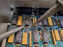
What I found was that the 4 pots on each little board in an
axis plug are associated with two test points on the counter
board in the cmm control (into which the plugs are inserted).
There are two test points for each axis. To adjust a given
axis, connect a scope probe for the 'upper' waveform (i.e.,
the one associated with the upper two pots when looking at
the plug board) to the upper test point and a scope probe
for the 'lower' waveform to the lower test point for the
axis. Set both channels to 2v/division on the scope and,
in auto mode, set the upper trace to the middle line of the
screen and the lower trace to the bottom line of the screen.
With power on and while moving the axis in question, you
should see sine waves from each channel. The top two pots
are used to adjust the upper signal (on the upper test pin
for the axis of interest). The upper pot of each pair sets
the offset of the waveform and the lower pot of each pair
sets the amplitude of the waveform. The following numbers
were derived by looking at the two good axes and served to
set the third so it now works perfectly. My z-axis voltages
were way off before my resetting and the fact that it
(mostly) worked for a long time indicates to me that these
are not terribly tight tolerance numbers.
top of upper waveform - 7.1 volts
bot of upper waveform - 2.7 volts
top of lower waveform - 3.5 volts
bot of lower waveform - 1.0 volt
---
Each scale unit has four pairs of emitters and sensors that
see out through a pattern of bars which one of the older
user manuals indicates are spaced a quarter space smaller than
the bars on the scale. It is easy to trace the wiring back to
the plugs and see that the pots on the plug are used to adjust
the voltage level to the emitters, apparently one per pot.
What isn't clear is how that translates to the two (unequal)
sine waves at the test points. These seem to form a
quadrature pair (the phase difference is clearly visible on
the scope) but how the circuitry gets from the four physical
signals to two logical ones is not clear to me.
This is for people who get a 'axis error' message on a Brown
and Sharpe MicroVal machine. I'm posting this for the next
person who has to deal with this - my problem is solved but
reply if you want to ask questions or discuss it. Also, if
anyone knows how to set the dip switches on the controller
board for one of these cmm's, I'm interested.
Mark
----
Adjusting Brown & Sharpe MicroVal CMM Axis Quadrature Signal
11/25/09 - m. mcdade
Each 9-pin axis plug contains a small circuit board with
four pots for adjusting the quadrature signal waveforms.
I did not trace out and understand the exact function of
the circuitry supporting the sensors but at the time of
this work, both the x and y axes functioned well while
the z axis produced a 'axis error' message. Cleaning and
resetting the sensors on the scales helped (several years
ago, cleaning completely eliminated an error on the y axis)
but, eventually, the z axis could not be used any more and
required adjustment.
What I found was that the 4 pots on each little board in an
axis plug are associated with two test points on the counter
board in the cmm control (into which the plugs are inserted).
There are two test points for each axis. To adjust a given
axis, connect a scope probe for the 'upper' waveform (i.e.,
the one associated with the upper two pots when looking at
the plug board) to the upper test point and a scope probe
for the 'lower' waveform to the lower test point for the
axis. Set both channels to 2v/division on the scope and,
in auto mode, set the upper trace to the middle line of the
screen and the lower trace to the bottom line of the screen.
With power on and while moving the axis in question, you
should see sine waves from each channel. The top two pots
are used to adjust the upper signal (on the upper test pin
for the axis of interest). The upper pot of each pair sets
the offset of the waveform and the lower pot of each pair
sets the amplitude of the waveform. The following numbers
were derived by looking at the two good axes and served to
set the third so it now works perfectly. My z-axis voltages
were way off before my resetting and the fact that it
(mostly) worked for a long time indicates to me that these
are not terribly tight tolerance numbers.
top of upper waveform - 7.1 volts
bot of upper waveform - 2.7 volts
top of lower waveform - 3.5 volts
bot of lower waveform - 1.0 volt
---
Each scale unit has four pairs of emitters and sensors that
see out through a pattern of bars which one of the older
user manuals indicates are spaced a quarter space smaller than
the bars on the scale. It is easy to trace the wiring back to
the plugs and see that the pots on the plug are used to adjust
the voltage level to the emitters, apparently one per pot.
What isn't clear is how that translates to the two (unequal)
sine waves at the test points. These seem to form a
quadrature pair (the phase difference is clearly visible on
the scope) but how the circuitry gets from the four physical
signals to two logical ones is not clear to me.


")