Hi everyone,
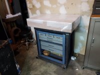
I'm building a cart for my 24x36 surface plate. I took a standard "work smart" metal cart, that's rated for 1200 lbs of load, trimmed it down to lower the height, replaced wheels with heavier duty ones and added the rubber feet. The idea is to have wheels and feet at the same time. When the feet are up, I can move the cart around, but if I need extra stability - I can lower the feet. That should also allow for precision leveling.
It may not be obvious, how the feet work. They are Sunnex adjustable mounts. Rotating the bolt, I can adjust foot height within 1/2". In "default" state, feet are all the way up and there is a gap of 1" between the feet and floor. If I want to lower them down, I should insert spacers between bottom of the cart and the feet. Height of the spacer is a little bit less than 1", so it squeezes in there freely. When spacers are in place, I can start jacking up the cart by rotating the bolts. After a while, the wheels will lift up and the cart will stay explicitly on feet. Dismounting is the same sequence, but in reverse. It may sound complicated, but in reality it's just a couple of minutes to switch between wheels and feet.
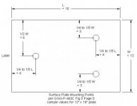
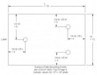
Now the question: I suddenly realized, that top of the cart is to flimsily for holding the surface plate. Event though it's rated for 1200 lbs, it will sag by significant amount if I just press in the middle of the top with my finger. My surface plate came with 3 shims at the bottom from the factory. If I just put the plate on the cart as is, those shims will "sink" into the top of the cart because it will deflect. This will cause the plate to be supported mostly on edges rather than 3 points, where it's supposed to be supported. Not to mention complete lack of stability - the plate will go out of level under any load placed on top of it. How do I reinforce the top so it doesn't sag? I thought about putting 2 rectangular steel beams underneath the top, but it's not clear, how to properly attach them to the rest of the cart.
Thanks!


I'm building a cart for my 24x36 surface plate. I took a standard "work smart" metal cart, that's rated for 1200 lbs of load, trimmed it down to lower the height, replaced wheels with heavier duty ones and added the rubber feet. The idea is to have wheels and feet at the same time. When the feet are up, I can move the cart around, but if I need extra stability - I can lower the feet. That should also allow for precision leveling.
It may not be obvious, how the feet work. They are Sunnex adjustable mounts. Rotating the bolt, I can adjust foot height within 1/2". In "default" state, feet are all the way up and there is a gap of 1" between the feet and floor. If I want to lower them down, I should insert spacers between bottom of the cart and the feet. Height of the spacer is a little bit less than 1", so it squeezes in there freely. When spacers are in place, I can start jacking up the cart by rotating the bolts. After a while, the wheels will lift up and the cart will stay explicitly on feet. Dismounting is the same sequence, but in reverse. It may sound complicated, but in reality it's just a couple of minutes to switch between wheels and feet.
Now the question: I suddenly realized, that top of the cart is to flimsily for holding the surface plate. Event though it's rated for 1200 lbs, it will sag by significant amount if I just press in the middle of the top with my finger. My surface plate came with 3 shims at the bottom from the factory. If I just put the plate on the cart as is, those shims will "sink" into the top of the cart because it will deflect. This will cause the plate to be supported mostly on edges rather than 3 points, where it's supposed to be supported. Not to mention complete lack of stability - the plate will go out of level under any load placed on top of it. How do I reinforce the top so it doesn't sag? I thought about putting 2 rectangular steel beams underneath the top, but it's not clear, how to properly attach them to the rest of the cart.
Thanks!


")

")