What's new
What's new

Haimer 3D Sensor internal disassembly pictures

TORE_BACK

Plastic
Joined
Mar 9, 2021
Hello.
After a z crash the haimer was sticking and not returning to zero. i found a lot of post on disassembly, but nothing of the internals so i thought i would share.

taking the indicator out of the housing is covered a lot so ill start where i couldn't find anymore info.

disassembling the indicator first remove the snap ring holding the bezel.
20210309_130710.jpg
work the ring free and the bezel will fall out when tipped upside down.

once the bezel is out there is an o-ring and a white plastic ring that holds down the outer gauge face plate. pic out the o-ring and the white plastic ring will fall out when tipped upside down.
20210309_130336.jpg

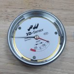
next work up the outer gauge face plate. you have to stress the large needle to do this so be gentle. on assembly there is a tab at the 25 mark. this keeps the faceplate rotating with the dial.
20210309_130022.jpg
20210309_120018.jpg
 

Attachments

  • 20210309_120009.jpg
    20210309_120009.jpg
    90 KB · Views: 84
Last edited:
once the outer face plate is off you will see the 3 screws that hold the outer dial to the assembly remove the screws and slide the spring tabes in towards the center. the outer dial will lift straight up once the spring clips are slid inward onto the brass.
fullsizeoutput_1.jpg
 

Attachments

  • 20210309_120435.jpg
    20210309_120435.jpg
    79.5 KB · Views: 43
  • 20210309_120009.jpg
    20210309_120009.jpg
    90 KB · Views: 45
once the outer dial is lifted off, the inner dial face plate can be rotated to uncover three screws that hold the indicator assembly to its housing. remove theses 3 screws.
20210309_120522.jpg
on assembly there are 2 sets of holes. the treaded holes are the spring clips for the outer dial, and the trough holes are for holding the indicator to the housing.

flip the assembly over and you will see two shcs these are the last two screws holding it in the housing.
20210309_131124.jpg
you also need to remove the strait head screw on the rack that holds the return spring. the spring will lift off the head of the other screw that's at 11 o'clock. no need to remove that one.
 
this was where my problem was. the pinion gear on the rack assembly was bound for some reason. i could not remove the top brass plate that was holding the pinion shaft without disassembling it. the indicator would not return up freely under its own spring pressure. i removed the two strait screws holding the plate, and could pry up a little freeing the shaft. it would then return up no problem.
20210309_115926.jpg

with the needles facing down go to take the housing off the indicator. it comes up and to the left to free the slid pin from its green guides. when it is free the needles will unwind because of the spring wrapped around the gear shaft. don't worry you will wind back in some spring pressure on assembly.
20210309_120757.jpg
20210309_120801.jpg
i removed the top brass plate that holds the pinion shaft cleaned it and put it back on. that fixed my problem. i don't know why it was bound or what fixed it, but this was as all it took for me so i reassembled from here.
 
reassembly took both hands so i don't have pictures, but if you took it apart you should have a good idea on how it slips back in.

the main thing is clocking the pinion to the rack. wind back in a little spring pressure not a whole lot or the spring will jump up. the main return spring should do most the work after its assembled.

you need to wind in the pressure by turning the pinion gear.

clock the inner gage face plate so it is in the correct orientation. the three holes in the face plate line up to the threaded holes for the spring clips, and the notch at 12 o'clock
20210309_120009.jpg

is is difficult to hold the face plate at this location when you wind in the spring pressure so you can put one screw back in and clamp the face plate a little.

wind in a little spring pressure and clock the needles(your clocking the needles just by turning the pinion gear i never disengaged any of the needle gearing). wind it until the little needle reads just past -.10
20210309_120009.jpg

the hard part is holding it here while you put it back in the housing. i held it one handed with the needles facing down and my finger tips stoping the big needle from traveling.

with the outer housing in your other hand use you index finger on the pin facing up to manipulate the rack assembly. this picture for orientation reference, but the rack needs to be in the down position when it in-gauges the pinion. not up like the picture.
20210309_120801.jpg

the housing slips down over the top of the indicator coming in from the left to get the slide pin in its guides first. make sure the indicator is seated in the housing and the pinion is in contact with the rack before you let go. other wise the needles will unwind.

next you can put the return spring back on the rack, and the two shcs to hold the indicator in the housing.
20210309_131124.jpg
 
Last edited:
Thanks for posting that, I wondered what the guts looked like


Sent from my iPhone using Tapatalk Pro
 
next flip the indicator over. needles facing up. and put back in the the strait head screws. these are the ones through the trough hols. they secure the face plate side of the indicator to the housing. rotate the inner face plate around until the hole in the faceplate lines up with the through holes and drop the stew in. when you tighten make sure not to clamp down on the face plate. rotate the face plate around to get all three.
20210309_120522.jpg

next is the outer dial. i placed the indicator back in the body because it holds it nice for this step.
20210309_123832.jpg
clock the face plate to the correct position and the three holes for the spring clip will line up with the face plate.

the spring clips orientation with washer.
20210309_123611.jpg

the next part is a bit tricky. you need to slip the spring clips between the face plate and the brass with the washer in place. they need to slide in enough to clear the dial, but leave enough of the hole showing to get them back up over the dial once its in place. also keeping the face plate in the correct orientation.
20210309_120435.jpg

after all the spring clips are in and on the brass you can drop the outer dial on. i used a dental pick to get under the spring clips. bringing them up on to the outer dial. then screw them down. again make sure not to clamp the faceplate
20210309_125139.jpg
 
after that its just the outer gauge faceplate and bezel assembly.
20210309_120018.jpg

make sure to get the tab at the 25 mark back in the hole on the outer dial.
20210309_130022.jpg

place the outer white plastic ring and seat the o-ring back on top of that. drop the bezel in and secure it with the snap ring.

place the indicator back in the body and zero the needle using the 4 grub screws around the dial.

anyways hope that helps someone from just buying a new one. sorry in advance for all the grammatical errors :dunce:.


Back
Top