What's new
What's new

Help with how to make a particular measurement

opscimc

Stainless
Joined
Jan 24, 2012
Location
Southwest
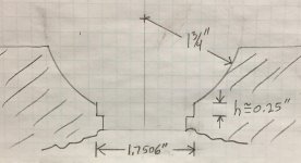
I'm hoping one of you can help me with a good suggestion for determining the height 'h' in the attached, cylindrically-symmetric scale drawing to an absolute accuracy no worse than 0.001". That is, the height from the edge of the hemisphere (the edge is sharp, not rounded off) to the ledge that is approximately 1/4" below. The diameter of the cylindrical depression whose height I need to measure is actually 1.7506", but at this point I only know the radius of the hemisphere to approximately +/-0.016" (1/64").

drawing03.jpg

Although I drew a line across the bottom, it's actually open at the bottom and I don't have access to it anyway since this is part of a larger structure (i.e. I couldn't rest the object on the bottom and use that surface as a reference).

Assume I have a pretty comprehensive set of micrometers, height micrometers, gauge blocks, surface plate, etc., but no CMM.
 

Attachments

  • drawing.jpg
    drawing.jpg
    85.6 KB · Views: 132
Last edited:
The other principal is the use of a "gauge object" - for example a pricisely sized gauge ball, and precisely sized plug. The ball is sized such so that it will catch on the circle at the top of height h. You measure from a surface plate to the top of the ball. It's a gauge ball, so you know it's size very accurately - do some math (I like to use cad for less confusion) and that will tell you the height of the top of h. This of course depends on knowing the diameter of the bore of height h - you measure that with gauge pins or the like.

Now get a plug, a gauge pin would work well if you find one large enough, said plug is large enough to rest on the shoulder at the bottom of h, small enough to not hang up at the top. Again measure from a surface plate. Again do math against the well known height of the plug.

This all adds up to a string of measurements and therefore sources of error, it will be hard work.
 
I'm confused. Is the remaining material inside the hemisphere or outside the hemisphere?! Initially, I thought inside, but now I am thinking this is a cavity not a stud.

Either way, I suspect you will need to know the diameter of your spherical surface to a lot better than 15 thou if you want trigonometry to give you an answer to 1 thou or better.

Assuming this is a cavity, you can make a right cone of known angle to rest on the ledge. Then use balls of known diameter to get a geometric relationship between the ledge and the sphere. Using two (possibly three) different sets of balls, of different known sizes, you can probably solve for the size of the sphere and then for the height of the center of the sphere above the ledge. Then you can solve for the intersection of the ledge wall and the sphere. But I'm not going to do the trig in my head before afternoon coffee. :-) That "right cone of known angle" needs to be toolmaker-grade. The angle can be whatever is convenient, but needs to be accurately known. Surface should be ground, and the base ideally will be centered by a no-shake slip fit against the ledge walls.
 
Thanks for the responses so far. I'm sorry my drawing was ambiguous, but I hope the following one clears up possible confusion.

drawing03.jpg

It's an internal feature, the hemisphere is not a full half-sphere, the top surface is available to use as a reference, but the bottom one isn't.
 

Attachments

  • drawing02.jpg
    drawing02.jpg
    87.9 KB · Views: 74
Make a gauge. For example, a cylinder 1.7506 (or 1.7505" diameter and 0.25000 tall. Put the work workpiece on a surface plate, and using jacks and wedges make the top reference surface Very Level. Now, using a long arm on a height guage, with a descending arm, probe the top of the shoulder - and call that zero. Next, insert the gauge. Probe the top of that - the difference should be 0.250 if the part is good.

If you don't have a "big" height gauge (meaning tall enough and long enough reach) but are making this on a VMC with a probe, use the probe, understanding systemic errors in the machine will affect this too.
 
, but at this point I only know the radius of the hemisphere to approximately +/-0.016" (1/64").
That becomes a problem as the start point all over the place.
Retro rubber a great one piece check but what on the next when the start moves .016?
One part, a hundred, 20,000?

Assume a cnc machine tool VMC or other. Is there software out there out there to make your machining center with a probe act like a low accuracy CMM.
The whole deal and fancy math of what a CMM does but done in a machining center not the simple x-y stuff but as here curve/wall.
There must be something, if not seems like a market.
Bob
 
It seems to me the issue the hemisphere creates is a ledge whose position is difficult to determine accurately, which in turn makes it difficult to determine the height h accurately. If it were flat at the top of 'h' the measuring problem would be simple. The drawing is to scale so it can be seen that the hemisphere intersects the edge of 'h' at ~45-degrees. This means every 0.001" I'm off in determining the true edge, the height also would be off by 0.001".

Maybe the above, plus geometry, gives an answer. I can determine the position of the wall of 'h' to better than 0.001" in my mill. I could then move the piece in one direction and determine the height of the ledge at the bottom of 'h', and then move it in the other direction to, say, 0.005" past the wall and determine the height of the hemispherical surface there. From geometry, and the radius of 1¾", I could calculate the height at the wall itself (i.e. the "correction factor" would be ~0.005"). I'd want to think about it for a minute, but I think the present uncertainty in that 1¾" value would have a relatively small effect on the calculated correction factor.

Any thoughts on the above? Or other ways of approaching the problem?

All the geometry is for nowt if the sphere is imperfect, and you know not where and how, so how was THAT vetted?

Or has it NOT yet been vetted?

Might consider replacing the person who designed it without including a bespoke gauge to vet the process and/or engineer a way to reference it right into the design!

A wiser "self" with a new perspective can be considered as a replacement?

:D

I can't believe someone MADE this sucker first.. and didn't plan ahead for the NEXT step .... gaging it and putting it to use or to a mate - that is NOW busting your chops?

Or did you NOT make it, just "inherit" it as a Christmas puzzle for accumulated sins, 'stead of a lump of coal?

:D

You have some gauges to make to be able to put geometry and math to WORK.

Even GOOD "general purpose" manual metrology will need such aids.
 
1.75" is wide enough to install a mirror. You can lay rings of known height in the sink and have a look at the edges, whether they match or not. Simple.
 
what about a ball gage of approx 1.75" radius (just enough smaller than the hole to fit into the hole and hit the top edge of h. Simple geometry gets you the top of h value relative to your surface place by measuring the top of the gage ball relative to the surface plate and measuring the diameter of the hole at the h perimeter allows you to calculate at what point the ball gage hit the h edge. Then gauge block of known length set on bottom edge of h but protruding above opening gets you the bottom edge of h using height gage relative to the surface place. Then just do the subtraction.
 
1.75" is wide enough to install a mirror. You can lay rings of known height in the sink and have a look at the edges, whether they match or not. Simple.

"Something along those lines", yes. Could be cylindrical tubes, inner and outer slip, measure the difference, deck and at-depth.

One way or another, make some gauges, or adaptors that attach to existing goods.

Concept probably began with flint arrowheads needing to be reasonably similar, complex shape or no, in order to put game animals in the stew pot... lest they all shoot too differently and miss, starve the tribe.

:(

Presume you have a decent lathe, good metrology, you make a buncha, vet THOSE simple things "easily".

Experiment until you have a subset that is "just right" for least-hassle reading.

Mark those, store them as bespoke gauging for THAT TASKING.

Should beat chasing yer loose balls all over the bench and shop floor, yah?

:D
 
Depth micrometer will locate the bottom of the counterbore relative to the top surface. Gage ball will allow you to locate the center of the spherical feature relative to the top surface. With that and a bit of math you can determine the dimension you are trying to inspect. Consistent and accurate measurements of the diameters of these features are critical and will determine how accurate your inspection is.
 
Depth micrometer will locate the bottom of the counterbore relative to the top surface. Gage ball will allow you to locate the center of the spherical feature relative to the top surface. With that and a bit of math you can determine the dimension you are trying to inspect. Consistent and accurate measurements of the diameters of these features are critical and will determine how accurate your inspection is.

Or.... One could attach a decent dial bore gage to a stout vernier height gage .. ascertain depth at which max bore is read for a datum line.

If need be, vernier not good enough, there is one each (inch) Cadillac Gauge Pla-Chek, (metric) Starrett-Weber Digi-Chek, and (inch) B&S Height-i-cator in the arsenal.

Always more than one workable way. Alway an infinite number of NON-workable approaches!

If it was EASY.. Machinists would do it..

Hang on.... ?? Does that sound right?
 
As CarbideBob asked, 1, 100, or 20,000?

If the production and value of the part justifies it, I would get a set of pins from minimum to maximum allowable diameter of the bore, grind them to the same height (or carefully measure and note the height of each) and make a precise cone: with the pins you measure both the depth of the feature and the diameter of the hole. With the cone you measure the position of the edge, given the diameter.

If you are dealing with only a handful of parts, I would make a Repro Rubber cast.

Another alternative is to make a "plug" exactly .250" high, slip-fitting in the cylindrical feature, and with sharp edges on the top (the bottom edges should be rounded to accommodate any radius at the bottom of the cylindrical portion): mount a tenth test indicator on the height gauge and probe the junction of the spherical portion with the plug: if the tip of the indicator is small enough, you will observe a "bump" in the transition if the feature is not exactly .250" deep and you could qualify the error as being clearly less than .001" or not.
This of course is acceptable only if you are both the maker and the customer. It could be good enough to satisfy yourself that the piece is good enough, but does not provide you any acceptable figure to send it back to the maker.

Paolo
 
One more way to determine "h" dimension.
You would need to buy one ball, the size of which would be a radius of at least as small as the minimum hemisphere radius that you think you have. You would have to be sure that it locates on the transition point of the radius and the "thru hole" If it wedges in the "mouth opening it's too large or the hemisphere radius is too small.
Being that it locates on the correct point we now know the chord length (1.7506) and the radius of the ball.
We can then calculate up from there to the top of the ball, then measure down to the top of the part, then down to the step, the difference being "h" dimension.

Eugene


Back
Top