What's new
What's new

Measurement of nuts and screws

mkpash

Plastic
Joined
Apr 1, 2020
Hi Guys,

we are having trouble with convincing our supplier that our rejections for screws and nuts are valid.

basically we are using calibrated Thread Calipers as our main inspection instrument. However, when the same rejected screws are checked on a calibrated caliper at supplier, they are OK. My questions are as below:

what is the best/most thorough method of measuring screws out of below?
a. External Thread Caliper gauge,
b. Thread Parallels contacts (we currently don’t have thread micrometers),
c. Thread Pitch gauge
d. Go/NoGo Ring Thread gauge

Also for nuts we are using calibrated Go/NoGo plug gauge but even then it is not a valid rejection as per supplier.

How can we justify our inspections and convince supplier that our rejections are valid?

Regards,
Mustafa
 
Mustafa,
How is the supplier measuring the fasteners to arrive at the conclusion they are OK? Absent more information, I would think that calibrated ring and plug gauges are the right tools, with thread wires and micrometers a close second for the male threads. Thread mics are better used as process gauges, rather than QC gauges, in my opinion.

Maybe you can get the supplier to send you a mobile phone video showing how the fasteners fit and don't fit the go and no-go gauges, then have them send those same fasteners so you can check them with your gauges and see whether you get the same answer. Is the supplier halfway around the world or across the shire?

Regards and be safe and healthy,

RKlopp
 
Hi RKlopp,

Supplier is using the same methodology as we are using ->Thread Calipers and Plug Gauges
We did make a video as you mentioned. Video clearly shows that the NOK parts measured on our caliper are OK on supplier's caliper
Both having been certified to UKAS by the same company.
I am inserting the video here. Blue one is supplier gauge, black one is ours.
Now i don't know how to take this further..should we change our measuring methods?

Regards,
Mustafa
 
The gauge alone may not tell all needed about the thread. I would also use a three wire and micrometer check. It is possible the fail is from the flat or radius of the thread at the minor diameter. You can look at the fail screw and gauge with a 10 power loop and see where it fails. You may need work that out with the supplier.

You have to know the specification for that size in grade required, measure those features and find what feature they are failing.

UN imperial screw thread calculator

Metric screw thread: M Profile calculator

Basic is:
Major diameter:
Pitch diameter:
Minor diameter:
Over wires:

Best is that it is a catalog thread /one that specifications can be found. of it is an oddball or special thread you and the supplier will have to work it out.
 
Tolerance and what is a bad check?
Do know a six sigma on your checking?
I think you are asking to dive into world you not want tread in.
Work with your suppliers. My check vs yours, neither good or bad, Do not walk in with your parts are poop and my measuring is right.
It is how do we sort this out and work together.
Bob

If we are checking with calibrated gauges, our rejection should be justified? it not about supplier mistake, maybe its our inspection method needs to improve? my question was what other ways are effective in doing so..
 
The gauge alone may not tell all needed about the thread. I would also use a three wire and micrometer check. It is possible the fail is from the flat or radius of the thread at the minor diameter. You can look at the fail screw and gauge with a 10 power loop and see where it fails. You may need work that out with the supplier.

You have to know the specification for that size in grade required, measure those features and find what feature they are failing.

UN imperial screw thread calculator

Basic is:
Major diameter:
Pitch diameter:
Minor diameter:
Over wires:

Best is that it is a catalog thread /one that specifications can be found. of it is an oddball or special thread you and the supplier will have to work it out.

its a COTS M8 screw commonly used in industries..please tell me more about 10 power loop?
 
Unfortunately, you don't get a measurement with a GO/NOGO gage, you only tell if it is smaller/larger than the gage. The gage tolerances are designed so that if the screw passes the GO/NOGO gage, it meets the tolerance of the standard. In order to accomplish that, the size range allowed by the gage must be smaller than that allowed by the standard. It is entirely possible that an in tolerance part would pass their GO gage, but not yours.

The first thing I would check is if your thread gage has been calibrated, then check if theirs has. If you aren't comfortable accepting parts that pass their gage but not yours, you'll need to measure the threads and determine what size they actually are and see if it's in tolerance. The traditional method of doing that is thread wires and a bench micrometer with a pressure controlled tailstock.

If you want something easier to use, almost as easy to use as a GO/NOGO system, but gives you an actual number, check out the tri-roll system. It tells you the deviation from nominal and they program in the tolerance bands. Largest Gage Manufacturer in the US.

The other option you might have if you want to maintain control of the measurements would be to provide the gages. I assume these are a custom part you are having made. You could get two gages, one your you and one for them. Pick the one with the smaller tolerance band and give it to them. Since your gage's tolerance band is larger than theirs, you will never fail a part that they passed unless something is long with the process or the gage. I don't remember the exact numbers, but when making custom GO/NOGO gages the advice used to be to make the gages for shop floor to cover 80% of the tolerance band, and the gages for the inspection room to cover 90% of the tolerance band. This ensured that a part that passed with a shop floor gage shouldn't be failed by inspection unless something is wrong with the gages.
 
I just read your that it's an off the shelf part. ISO 3269 Fasteners - Acceptance inspection, points you to ISO 1502 ISO general-purpose metric screw threads — Gauges and gauging. Here's what it says on inspection gaging:

5.3.2 By the purcheaer

There are three possible procedures, as listed below, for inspection of workpiece threads on behalf of the purchaser by an inspector who does not belong to the manufacturing plant concerned.
a) The inspector gauges the workpiece threads with the manufacturer’s gauges.
In this case, the accuracy of the gauges used may be checked by means of check plugs and setting plugs which belong either to the manufacturing plant (manufacturer) or to the inspector (purchaser) or, as far as screw plugs are concerned, by direct measurement.

b) The inspector uses his own gauges for gauging the workpiece threads.
In cases of dispute it is recommended that the product be accepted if it is shown to be satisfactory by any gauge of the type concerned known to be within the requirements of this International Standard (taking into consideration the admissible wear).

c) The inspector uses his own inspection gauges for gauging the workpiece threads.
The position of the tolerance zone for these gauges shall be such as to ensure that the purchaser does not reject threads whose actual size lies within the limits specified for the workpiece.

This International Standard does not specify which gauges are to be used by the inspector; it only recommends that the purchaser inform the manufacturer when ordering what procedure will be employed for the inspection of the workpiece threads. Worn gauges shall not be used for sample inspection.


So if you have two gages that disagree, it recommends using the manufacturer's.

However, it says later that if there's a dispute, you shouldn't use a caliper gage, you should use a ring gage, preferably solid.

Unrelated to your dispute, it does recommend that if you're using a caliper gage, you should additionally check a percentage of them with a ring gage, as the caliper gage can miss some types of errors.
 
the basics of metrology... is the temperature, RH, and particulate count controlled and specified in related documentation? is the method and standards traceable for all parameters? :D I doubt particulates are the problem, but you get the idea, just because two gauges meet "a standard" really doesn't mean much.

if you don't know what a 10X loupe is, well look it up. without at least that level of equipment for inspection, consider your self TOTALLY in the dark.
 
Hi Guys,

we are having trouble with convincing our supplier that our rejections for screws and nuts are valid.

basically we are using calibrated Thread Calipers as our main inspection instrument. However, when the same rejected screws are checked on a calibrated caliper at supplier, they are OK. My questions are as below:

what is the best/most thorough method of measuring screws out of below?
a. External Thread Caliper gauge,
b. Thread Parallels contacts (we currently don’t have thread micrometers),
c. Thread Pitch gauge
d. Go/NoGo Ring Thread gauge

Also for nuts we are using calibrated Go/NoGo plug gauge but even then it is not a valid rejection as per supplier.

How can we justify our inspections and convince supplier that our rejections are valid?

Regards,
Mustafa


when we check threads we do the following.

Check the Major dia with a micrometer in a few places around the major.
Check the Pitch dia with calibrated thread wires in 2- 3 places. every xx amount of parts per your inspection plan.
check with go and no go gage (machinist should be doing this also on the bench while running them) this is more of a functional ability check.
Check thread profile in a Comparator. This sill check root rad/ form etc that you can pick up on a thread gage
Check for the proper thread chamfer and Thread relief
then visual check to make sure your finish is acceptable.
its common Practice for the company to supply there calibrated thread gages to there suppliers.

when suppliers use there own thread gages that causes problems as The company buying the parts of no control of the gage to check them with. which the supplier 0f the parts could have a 20 year old gage, never been calibrated thats been used a die and out of tols.

if you follow Standards you will very rarely have problems with threads being bad.
There are instances where 2 thread gages wont agree as they could be just a .0001-.0002 difference. (which means your running a tight thread to begin with.
The feel of the thread gage to each individual is different.
Checking with Thread wires Eleminates the thread gage issue above.
 
Hi Guys,

we are having trouble with convincing our supplier that our rejections for screws and nuts are valid.

basically we are using calibrated Thread Calipers as our main inspection instrument. However, when the same rejected screws are checked on a calibrated caliper at supplier, they are OK. My questions are as below:

what is the best/most thorough method of measuring screws out of below?
a. External Thread Caliper gauge,
b. Thread Parallels contacts (we currently don’t have thread micrometers),
c. Thread Pitch gauge
d. Go/NoGo Ring Thread gauge

Also for nuts we are using calibrated Go/NoGo plug gauge but even then it is not a valid rejection as per supplier.

How can we justify our inspections and convince supplier that our rejections are valid?

Regards,
Mustafa

Let’s take this one step at a time. For the moment I’ll assume the pitch is not a problem.

A standard M8 has a pitch of 1.25mm.

What is obvious (to me) is that the parts are very close to the tolerance limits. 2 gauges are never identical so the slightest variation (when close to the tolerance limit) will get the result you’re dealing with.

Re “calibration” of the gauges. Is actual measurements given on the certificates or just a “within spec”? If the latter then there is a tolerance on thread gauges just as there is on threads, just much less of course.

What I’d do, and recommend you do, is to start by measuring as much as you can on a number of threads. It’s easier than it seems. What you’re looking for is the measurement distribution and where the measurements are with regard to the tolerance.

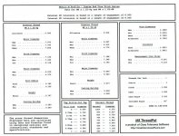
The enclosure gives all the necessary information re an M8 thread.

M8.jpg

Thread denominations

thread denominations.jpg

Measure the number of items necessary to see a distribution. Note each measurement on an X diagram or similar.

External M8.
The easiest to measure the OD (d) is with a micrometer or caliper. The tolerance is 0.212mm so this should be no problem.
The next is the pitch diameter (d2) and here you can either use wires or my inserts. Probably cheapest with wires. The d2 tolerance is 0.118mm.

Internal M8
The easiest way to measure the hole (D1) is with a caliper. The tolerance is 0.265mm so this should be no problem.
Measuring the pitch diameter of an M8 internal thread (D) can be a problem. I have inserts that can do this but it's your supplier that should be using them and not you. The D2 tolerance is 0.160mm.

YouTube

What you are doing, if you do what I suggest, is finding the manufacturing distribution on the threads. I’m as good as convinced you’ll find at least one of the tolerances is right next to the tolerance limit.

If your supplier is to be blamed for anything then it’s for not measuring and not staying away from the tolerance limits. He is mass producing so it should be a no brainer to measure rather than inspect.
 
A 10-power loop is simply a magnifying glass very often used by jewelers to examine diamonds.
They are also used by machinist and tool makers to see very small features of parts and gauges.
NEW 30X 10X Triplet Coin Jewelry Eye Loupe Magnifier Jewelers Diamond Loop US | eBay

A 3 wire set
TESA BROWN & SHARPE 599-4816 Thread Measuring Wire Set,3-48TPI,48 Pc 622419270449 | eBay
A thread micrometer might be used to check root diameter for a 60 degree thread
0- 1" Screw Thread Micrometer .0001" Graduation Anvil NEW | eBay

A machinist handbook is handy.Machinerys Handbook 19th Ed 1974 Machinists Information Book Guide Lathe Mill | eBay
 
Do you mind explaining how you can measure accurately with a standard 2 digit resolution caliper to 3x decimal places and a calibrated (spec) accuracy far below a micrometer?

Also, for high volume (SPC), standard practice is to reduce the tolerance window and use functional gauges.
Measurement is usually only a spot checking (1 in however many) because of time.

You can't resist can you?

Try reading my entire post and think before you post. It isn't about measuring to a third decimal place, it's about finding a distribution. A dimension is too close to the tolerance limit. The question is WHICH ONE.

You seem to think you have special knowledge from working within aerospace but so have I. In fact many of my present customers are within the aerospace industry. The OP's issue has nothing to do with aerospace, it's a common thread that's mass produced.

If you have something that'll help the OP with his issue then post by all means. If not don't post or it'll be deleted.

Important.

Your "Also, for high volume (SPC), standard practice is to reduce the tolerance window and use functional gauges." is incorrect.

SPC requires measurement, not Go/NoGo. I agree with you re "reduce the tolerance window". If a gauge is used then all you know is that something is not right but you don't know what until you measure.
 
A 10-power loop is simply a magnifying glass very often used by jewelers to examine diamonds.
They are also used by machinist and tool makers to see very small features of parts and gauges.

A 3 wire set
TESA BROWN & SHARPE 599-4816 Thread Measuring Wire Set,3-48TPI,48 Pc 622419270449 | eBay
A thread micrometer might be used to check root diameter for a 60 degree thread
0- 1" Screw Thread Micrometer .0001" Graduation Anvil NEW | eBay

Gordon B. Clarke has thread gauges at his site

It's the OPs supplier that should be measuring and not the OP. I'll just add to what you've listed that a profile projector is good for external threads but I doubt if the OP has one or it would probably be used.
 
QT: [It's the OPs supplier that should be measuring and not the OP
Sounds like they are going back and forth on this with not solving the problem..With the op able to tell what is wrong might help.

Op or supplier could pay someone to examine the part to find what is wrong.

In specification for the for the class should be the goal.

RE: (How can we justify our inspections and convince supplier that our rejections are valid?}
 
its a COTS M8 screw commonly used in industries..


Is this a knock off. trying to best the original manufacturers price and patent with not the knowledge or proper gauges.

If so both need learn about threads and gauging...and what is legal
 
Worldwide applications US52200834496A-1 ..... patent good world wide to 2027

________________________________________
Application US11/834,150 events
2006-08-11
Priority to US83733306P
2007-08-06
Application filed by Ferno Washington Inc
2008-02-14
Publication of US20080034496A1
2009-06-23
Publication of US7549690B2
2009-06-23
Application granted
2020-04-02
Application status is Active
2027-08-08
Adjusted expiration
 
Can't resist what?
Of course I've read you comment. And as you say the parts are close to the limit.
So measuring to see if parts are within limits when you're close to the limit, won't be achieved by a caliper with an accuracy of 0.04mm.
Calipers have their place but tolerances are there to be used - bad practice to reduce a window of measuring because of gauge inaccuracy.

Nothing to do with my background.
Stop threatening me.

All you're telling me is that you don't know how to use a digital caliper. Could be it's been decades since you even had one - if ever.

YouTube

My hands.


Back
Top