What's new
What's new

measuring whether my camshaft is bent

ozgeorge

Plastic
Joined
Apr 27, 2020
Hi all, I'm a beginner so please forgive me if this is an easy problem, but I'd appreciate some help.

I have a camshaft from a motorcycle and the tip has a thread which engages the timing advance mechanism. This tip has become bent (don't ask). I think I can fix this by facing it and tapping a new small hole on my minilathe HOWEVER, I would like to be sure that the camshaft itself isn't bent from the force that bent the tip.

I have tried to measure this by putting it in the lathe and using a dial gauge as shown and there is some variation as I turn the chuck by hand however I feel that this could well be due to the piece not being straight in the chuck. Does anyone have any better ideas to accurately measure this?

Please note that if I was to actually turn this I would use some kind of lathe steady with a bearing.

Thanks!

george
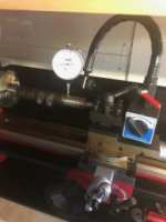
IMG_8110.jpg
 
This really should have been posted in the General forum as this isn't really a Metrology question.

First- You really want to check this accurately where and how much is "bent". Not knowing what bike you have I'll say that the camshaft spins in journals with caps that have very little clearance. Hope you marked which caps go where and which side goes forward as this important for most modern bike motors. A wear pattern is developed from OEM assembly and switching caps or orientation may severely affect longevity. The tight clearances between shaft/caps (consult your manual) demand that the camshaft be mapped for deviation.

Second- You should, IMO, check this on a surface plate and a set of matched blocks (flat or "V") to remove any possibility of misreading the variations caused by the machine like the chuck. Carefully set the camshaft on the matched blocks under the journal surfaces of the camshaft. Check the reading with an indicator. You'll want to use an indicator that reads to at least .010mm resolution. Rotate the camshaft and check for run-out at various points. It will take up to an hour or so but you don't want to rush through this. Compare results with allowed clearance limits in your manual will tell you if repair is even possible.

Third- Setting this up in your tiny Chi-Wan lathe for accuracy may/will be a small project in itself that will warrant a somewhat lengthy question/answer session. You really need to include exact descriptions with photos/drawings of what you intend to attempt if you want better advice. This is something that requires more than a casual approach if you want it to work well. It may work, it may not. We have no idea what you're going to try unless you offer more information.

Fourth- Start another post in the General forum with your information, we'll go from there. If this is something you intend to patch up so you can resell your hacked bike to some unsuspecting buyer then you're being an unscrupulous c*nt by asking for help to cheat someone else. If your intent is honest one of us will be willing to offer advice.
 
Jim nailed it. As long as you have centers, use them. You won't find an easier way to check. Any lathe with good centers can become a very adequate shaft straightness tester, doesn't matter if it is a toy lathe as long as the centers fit their sockets with no slop. And hopefully this goes without saying, but use dead centers.
 
Sorry, but centers won't help. His shaft is bent so even if it is straight along 95% of its length and only bent at the end, it will wobble if held between centers.

The photograph is tiny and dark so I can't see details of the cam. If there are sufficiently wide round surfaces (e.g. for the journals) at locations other than near the end with the bend, holding it in V-blocks and using an indicator is the first approach I would try.

p.s. I wouldn't take any bets that the OP would be able to face and tap the steel of that cam on his small lathe.
 
Sorry, but centers won't help. His shaft is bent so even if it is straight along 95% of its length and only bent at the end, it will wobble if held between centers.

Yes, but at least then he can see if it really is bent, and by how much. A start, you see.
 
Thanks everyone! sorry if this is in the wrong place- i figured problems with measuring something; metrology.

Looks like surface plate and V blocks is the way to go. Again, don't know why that wasn't obvious to me! thanks!

I'll let you all know how it goes.

with regard to actually repairing the cam (if i can convince myself it is still in alignment) you can see from this photo it's just the very tip (the threaded part) that is injured- i would cut this off and then have the tiniest nubbin to face, or I could just file it. Then just a 1/2in deep M3 tapped hole in the centre. I know the minilathe is not very powerful but i think it should be achievable if im careful. always interested to know people's thoughts.

thanks!
IMG_7386.jpg
 
I was going to say or a V block if not between centers..or if you can put it back in its own assembly under an indicator.. the photo doesn't tell much...I could likely straighten it with setting the nut only two threads in, and with a shim pack under it an arbor pres or a C Clamp to make it closer...
 
Big no on v blocks.

Between centers only!

We straightened hundreds of cams in a production shop.

The set of centers was not much more than a not-mentionable lathe looked like a tail stock at each end with a DI on a holder that rested on the ways.

It takes time and skill and remembering it travels TOWARD the hammer.

Sent from my SAMSUNG-SM-G930A using Tapatalk
 
i think he needs a steady rest. the nose is damaged, right?

george, try to post better, larger pictures.

tony, why no v-blocks?
 
V blocks support a bearing surface on a round section of the shaft.

If the shaft is bent then that round section center will no longer be in center of the shaft and your references are all bad.

The centers on the ends of the shaft are what was used to make it so they are the reference.

Supporting only by those it is easy to measure the travel off center of rotation.

Any minor bend anywhere will show up.

You measure the movement of the bearing surfaces and make corrections with chisel at the corner of shaft and bearing boss.

Gentle taping and an arc around the shaft.

It is SLOW so be gentle and tap once and measure as you need to sneak up on it.

They can and will go sideways so tiny steps keep things within control.

Sent from my SAMSUNG-SM-G930A using Tapatalk
 
It doesn't matter if a bent shaft wobbles everywhere when between centers. Find the point of maximum runout, use that spot to indicate and start working it towards zero. Between centers, the point of maximum runout is the location of the bend.
 
You stated "the" bend...

If lucky only one.

Shop we worked at was engine machine shop back in the day, did about 20 or so a day (straightened), most needed correction at every corner of the bearings.

It is not a difficult task as long as you take your time.

Sent from my SAMSUNG-SM-G930A using Tapatalk
 
Damn, why don't you guys LOOK AT THE PHOTOS, post 9 plain as day, it is clear that the end of the cam has been worked on by a rock ape, it is all mushed over. How the hell are you going to put it between centers? To the OP without a steady rest you have no chance of repairing it on your chi com lathe shaped object.


Back
Top