What's new
What's new

Position tolerance question.

SeymourDumore

Diamond
Joined
Aug 2, 2005
Location
CT
Guys, I'm having a brainfart here.

Making an absolutely idiotic looking part that is machined, then formed, then welded and then 2 final holes are added after everything else.

The two final holes are toleranced to be .2503-.2505 with a TP definition of:
j|n.005m|A|Bm|Cm

Where datums:
A is a flat surface
B and C is a hole on 2 separate planes

( damned, I thought I can cut/paste it in here ...)
Basically it says that the 2 holes must be W/in .005 (mmc) to surface A,hole B(mmc), hole C(mmc)

Now the question:
The datum holes B and C are +/-.01 diameter where
B = .3125 +/-.01
C = .375 +/-.01

What is my bonus tolerance???
Is it the .0002 given by the feature tolerance
or
Is it calculated independently for the MMC of each datum B and C, meaning
that if datum B was at basic .3125 then I get an additional .005 there
and
if datum C was at basic .375 I'd get an additional .005 there

In other words, is the bonus tolerance the given single feature MMC, or is it the sum of feature and datum MMC?

( If any of that ain't clear, please ask as this part is about to put me in the grave)
 
I think your post says 0.1 mm hole size tolerances, with 0.005 mm TP tolerance as goal.
The hole size tolerance gives you a 0.05 +/- error bar for 10x the accuracy intended.
Essentially impossible.
 
Nope, this is not metric.
The hole size is .2504 +/-.0001, while the positional tolerance is .005MMC ( Maximum Material Condition )
 
It is the sum. You get .005 if B and C are at MMC. As B gets larger than MMC, you gain positional tolerance on the target dim from B. Likewise with C.

(Actually .005 is at MMC also, but you're only going to gain a tenth or two on that)
 
Nope, this is not metric.
The hole size is .2504 +/-.0001, while the positional tolerance is .005MMC ( Maximum Material Condition )

How are you checking +/-.0001" ?? :eek: Doesn't that mean your gaging method needs to measure to .00001"

Curiosity as much as anything. We do some things down to tenths tolerance (which is more than we can physically inspect) that are "checked" by radio frequency or what not on some lab equipment, of which I know nothing about LoL.
 
your bonus on B and C is the difference between the minimum size and the actual size.

So if "C" measures .380 and the minimum dia is .365, you get a bonus of .015
 
Thanks Guys!

Mike, no, I am not actually measuring that with any certainty.
Those holes are for tooling balls to be used during assembly into the main component.

With that said, that is also just plain idiotic design that the tooling balls are positioned and toleranced based on other features instead of the other way around.:nutter:
 
This kind of callout can be tricky. You have to watch out for location errors on holes B and C. You have .005" to each feature at mmc, but they all have to come it at the same time.

That means there is potential for a mislocation of B or C to take away some of the position tolerance, especially if those holes are near mmc. A .005" position error on B will impact where you locate your tight tolerance holes to keep -A- and C in tolerance.

Something you want to know before you start. I like to do a layout on that kind of job, just to give me some confidence I know what I'm working with. ;)
 
Guys, I'm having a brainfart here.

Making an absolutely idiotic looking part that is machined, then formed, then welded and then 2 final holes are added after everything else.

The two final holes are toleranced to be .2503-.2505 with a TP definition of:
j|n.005m|A|Bm|Cm

Where datums:
A is a flat surface
B and C is a hole on 2 separate planes

( damned, I thought I can cut/paste it in here ...)
Basically it says that the 2 holes must be W/in .005 (mmc) to surface A,hole B(mmc), hole C(mmc)

Now the question:
The datum holes B and C are +/-.01 diameter where
B = .3125 +/-.01
C = .375 +/-.01

What is my bonus tolerance???
Is it the .0002 given by the feature tolerance
or
Is it calculated independently for the MMC of each datum B and C, meaning
that if datum B was at basic .3125 then I get an additional .005 there
and
if datum C was at basic .375 I'd get an additional .005 there

In other words, is the bonus tolerance the given single feature MMC, or is it the sum of feature and datum MMC?

( If any of that ain't clear, please ask as this part is about to put me in the grave)

I don’t know man . I am just glad to know someone besides myself have had jobs like this. We do not get appreciation, or good pay, nor even a bonus nor Thankyou. Good luck friend.
 
How are you checking +/-.0001" ?? :eek: Doesn't that mean your gaging method needs to measure to .00001"

Curiosity as much as anything. We do some things down to tenths tolerance (which is more than we can physically inspect) that are "checked" by radio frequency or what not on some lab equipment, of which I know nothing about LoL.

Who believes engineers anyway when they do this. Just take the job. Fact is that kind of thing scares away competitors. Just capture the work then work it out if a problem comes up.
 
The "M" after tolerance is not the same as "M" after datum. The "M" after the datum is maximum material boundary which cannot be just added to the positional tolerance. It is a datum shift.mmb1.jpgmmb2.jpg
This is from ASME Y14.5-2009
 
The "M" after tolerance is not the same as "M" after datum. The "M" after the datum is maximum material boundary which cannot be just added to the positional tolerance. It is a datum shift.View attachment 286958View attachment 286959
This is from ASME Y14.5-2009

Nano

Not sure why you're saying it isn't additive, but my positional tolerance is exactly like Option C: on your image.
The explanation clearly shows the sum of all other tolerances ( though it is called as maximum boundary )

With that said, thank you for the picture!
 
Nano

Not sure why you're saying it isn't additive, but my positional tolerance is exactly like Option C: on your image.
The explanation clearly shows the sum of all other tolerances ( though it is called as maximum boundary )

With that said, thank you for the picture!

The picture is just an example that this works out, but it's not alway so.
gdt1.jpg

There is way too much material to go over to explain this in depth. Look at ASME Y14.5 (I have 2009) in section 7 page 118.
 
The picture is just an example that this works out, but it's not alway so.
View attachment 287802

There is way too much material to go over to explain this in depth. Look at ASME Y14.5 (I have 2009) in section 7 page 118.

See!
I don't think GDT is all that difficult to understand, just need to learn some foreign English! :nutter:

Seriously, I'd rather read Fanuc manuals from cover to cover all day than trying to decipher that crap in your link!
Don't get me wrong, I very much appreciate your help, but Dammn! How drunk does one need to be not to get irritated by that kind of writing?

That crap in my link is the standard that almost every drawing in USA is calling up for interpretation. If you don't know the standard, you don't know how to read the drawings, and you don't know what you're making. LOL
 
First thing I saw at the start of this was that you were saying MMB instead of MMC. A subtle difference of the same symbol used in a different place, but an important one. MMC is pretty easy to calculate, MMB is a royal PITA. I've explained it this way in the past:

Say you have a fixture with solid pins that have to go through the holes, and all are in perfect position, orientation, etc. If it was straight up position, you would need expanding pins, so you add the (M) for MMB. This lets you used min size pins, but now things float. Of course when you go to mate the holes/slots up to this fixture they might be in the wrong spot, have form error in multiple axes, etc. Say the part has some thickness and hole C is crooked. This decreases the available float on the pin, and eats in to your bonus just as under sizing the hole would.

A "pass" is anything that goes on to this physical fixture, but if you were to say move datum B one way this would also decrease the slop to assemble, so that takes away from your bonus just as moving datum C would. If B and C move in the same direction you'll still have more slop (bonus) than if they moved opposite ways. Different forms of error (position, size and form, perp.) will have different impacts depending on which datum they are on.

I've discussed this somewhat extensively with a number of third party CMM shops and it always boils down to one of these conclusions:
1) They completely ignore it and pretend it doesn't exist, thereby rejecting parts unnecessarily.
2) They add them all up and give way more bonus than allowed.
3) They say "We just ignore that unless you give us a physical check fixture".
4) They say "Well, we would need a 3d model (already provided), and have to put it through our 3d fitting program (eg. PolyWorks), that would cost more". When I actually agree to pay for this extra step they revert to items 1 through 3 above.

At this point I highly discourage the junior engineers around me from using MMB unless they're going to build (and validate) a check fixture.

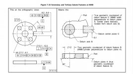
This picture may help. It references the same section that NV referenced above. The numbers are different because I'm referencing ASME Y14.5-2018 instead of -2009.

I agree that it takes some getting used to, but it really does make things easier once you understand it. It's been in wide use for several decades in the US now (and the ISO version outside the US), and conscientious lack of education to something standardized for this long isn't a great excuse. The language is tedious, but it's that way so as to be explicit. Preventing multiple interpretations protects everyone.
Y14.5-2018 Figure 7-26_.jpg
 
The language is tedious, but it's that way so as to be explicit. Preventing multiple interpretations protects everyone.
View attachment 287921

I think the word you're looking for is absurd instead of tedious. It doesn't just prevent multiple interpretations, it prevents ANY interpretation at all!
OTOH, your explanation was not only understandable, but absolutely logical.

For the record, I am not disputing the need, nor am I fighting the the system!
I am familiar with whatever I need to know, ask questions when clarification is needed.
This was one of those cases.
My customer choose Option 1 from your list and not only rejected it, but did so with an insane deviation.
I on the other hand chose Option 3 and made a checking fixture, which - curiously enough - passed with flying colors on their inspection.

I purposely tightened my MMC values considerably for the receiving gage ( basically cut every one in half ), and yet, the wildly out-of-spec part fit it
with quite a bit of slop.

Nonetheless, the issue is now resolved and the customer did their own education to come to the same conclusion.
 
I agree that it takes some getting used to, but it really does make things easier once you understand it. It's been in wide use for several decades in the US now (and the ISO version outside the US), and conscientious lack of education to something standardized for this long isn't a great excuse. The language is tedious, but it's that way so as to be explicit. Preventing multiple interpretations protects everyone.
View attachment 287921

Excellent explanation by the way.

My experience with the more esoteric elements of GD&T (and I mean everything beyond the extreme basics), is that regularly the only people in the chain who do understand them are machinists. The engineers who specify them frequently do not, and the inspectors who qualify the resultant parts frequently do not. Although I wear all three hats on occasion, I am primarily a machinist, and like many other machinists I bought books to learn it. Even now, mechanical engineers do not appear to be taught it at any stage of their education, which is kind of ridiculous.
 
That last part is a major issue. I, like every other engineer, like to think I went to a good engineering school. That claim has some national rankings behind it, but I only mention that to point out that we also had awful gd&t training in undergrad. We spent I think one day on it where they told us that they wanted us to have seen it so that we wouldn’t be totally green, but that since every employee uses it differently and thinks they are right, they would let us pick it up on the job. The problem with this is that it perpetuates people learning it by opinion instead of from the standard. I eventually got fed up, read the standard, and found all sorts of things my on the job training had gotten wrong. I’ve found since then that people tend to resist my interpretations at first. But come around really fast when I open up the standard and go through the relevant section with them, and of course I occasionally learn something too.
I do know one person who had to take a full dedicated course on it for their degree, and they understand it well. Unfortunately there is only so much space in a curriculum, so few places to this.


Back
Top