What's new
What's new

How to check two half-bores for colinearity.

wmpy

Hot Rolled
Joined
Dec 16, 2011
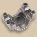
I’m looking for some ideas on how to check a part. It looks VERY similar to the part in this link.

Yukon Gear & Axle YY D44-1310-26U Pinion Yoke | Walmart Canada

I need to check the relation of the two half-bores. Their centerlines need to be colinear within a specified tolerance.

How would you check that? I do not have a CMM. I can check in the machine, but that has its pitfalls.

The machining done to the part is the first operation on a forging, so there are no other machined surfaces to reference other than the four faces with the bolt holes in them that I am machining in the same operation.

Nothing we have tried has given readings that I am confident in. Hopefully, someone out there has come across this situation before. Thanks!
 
What machine? That part looks small enough that you could bore it in one setup?


Sent from my iPhone using Tapatalk Pro
 
We'll be doing it on a horizontal machining center. The bores each have a step in them at the outer edges of the part. So, we back bore one side. Rotate it. Then back bore the other. That's the plan, at least. If the two bores are out of line, we can adjust for that. It's just difficult to measure.
 
Is this your own product or are you doing it for a customer? If for a customer, how are they going to check it? If just for you, is a go-nogo subjective measurement OK or do you need quantifiable traceable measurements?
 
I would stand the yoke up on the surface plate. turn up a pin to fit the half bores and then sweep across the pin with a DTI. You can use spot blue and press down with a finger on each end of the pin, to see how the blue rubs off. That will tell you if its in the same plane. I've used a few of those yokes myself (fabbing my own driveshafts...) so you do have a little room to play.
 
I would stand the yoke up on the surface plate. turn up a pin to fit the half bores and then sweep across the pin with a DTI. You can use spot blue and press down with a finger on each end of the pin, to see how the blue rubs off. That will tell you if its in the same plane. I've used a few of those yokes myself (fabbing my own driveshafts...) so you do have a little room to play.

My strategy would be rather similar. But, instead of one pin, I would use two identical ones, one for each half bore and you need to check for any "bump" where they meet (i.e., if the bores are co-linear, the test indicator would pass from one pin to the other without variation).

Paolo
 
Is this your own product or are you doing it for a customer? If for a customer, how are they going to check it? If just for you, is a go-nogo subjective measurement OK or do you need quantifiable traceable measurements?

It's for a customer. They are checking with a CMM. We have provided samples that we thought were good. Their findings were that the bores were not concentric. After talking to them about their process on the CMM, we have doubts about how well they're checking it. We don't need traceable, but quantifiable would be good so we know how to make adjustments.

Edit: Actually, a GO/NOGO gage would be great for production to give the operator an easy way to make the check. I'm just not sure what that would look like. We would still want a way to quantify the error, though.
 
Last edited:
My strategy would be rather similar. But, instead of one pin, I would use two identical ones, one for each half bore and you need to check for any "bump" where they meet (i.e., if the bores are co-linear, the test indicator would pass from one pin to the other without variation).

Paolo

I'm leaning in this direction. To complicate matters, our method of workholding is bending the part a little during machining so that once released, the bores are slightly angled to each other. I think the two pin method would be able to quantify this. I just have to figure out a fixture to hold the part while these checks are being made.
 
Perhaps a precision bushing resembling a drill bushing to closely fit one bore, and a clamp to hold it without distorting it. Then a close fitting shaft in the ID, and attach a test indicator to the shaft to indicate the opposite bore. You could extend the bushing out the end of the part if you groove it to clear the step at the outer edge. There are some very small indicators, I'm thinking of the old BestTest and similar.
 
Perhaps a precision bushing resembling a drill bushing to closely fit one bore, and a clamp to hold it without distorting it. Then a close fitting shaft in the ID, and attach a test indicator to the shaft to indicate the opposite bore. You could extend the bushing out the end of the part if you groove it to clear the step at the outer edge. There are some very small indicators, I'm thinking of the old BestTest and similar.

Mud,

We actually already did exactly what you describe. Unfortunately, it didn't work. We couldn't get the bushing to clamp into the bore consistently. Actually, we're having problems getting any pin to clamp into those bores consistently. If you zoom into the picture, you can see that the bottom of each of the bores has a large void in them. I don't know the purpose of this- maybe so the user can stick a screwdriver in there and pop out the U-joint. Anyway, it causes the pin/bushing to rock in there. We just can't get it to sit the same way every time. It doesn't matter what size pin we use. There just isn't enough meat in there to give a good seat for the pin.

Still trying to figure this out...


I believe it. I'm real familiar with pinion yokes and other driveline parts. Lots of automotive parts are made with really hazy alignments and tolerances and still work fine, and I find that disturbing from a machinist/designer perspective. That's why race cars parts exist - to improve on that, right? So... if you can't get a measurement device to clamp in there accurately in a machine shop, how the hell is anyone going to get the cross bearing cup to clamp in there accurately out in the field? I figure the cross is holding the bearing cup in alignment during installation, then the U-bolt clamps it in position. If this is true, your customer is chasing a detail that either doesn't matter or can't be reliably checked. Or both. Maybe try just bluing a pin that fits both saddles and seeing what the pattern is?

I wish you luck, and please keep us informed on how this is resolved, ok?
 
To complicate matters, our method of workholding is bending the part a little during machining so that once released, the bores are slightly angled to each other. I think the two pin method would be able to quantify this.

I think that may be a large part of the problem. How are you holding it? I imagine if I was doing the job in the mill, I would have it chucked into a H/V rotary table by the spline end.

On a lathe, I would bolt it to a sacrificial angle plate using the U-bolt cap screw holes on the part. Bolt the angle plate to the face plate, and bore the holes that way.
 
That yoke was designed to have the cup seat profile and the tops of the lugs cut with a surface broach. The relieved area at the bottom of the cup is so the shadow area from the locating lugs doesn't have to be machined.

What tolerance are you required to meet? What is the exact specification, including all modifiers. There are lots of ways these features could be dimensioned and the devil is in the details.

You have to fix your workholding method. You will never make consistent parts clamping over air.

Unless your bore axis is on the centerline of rotation you are going to have problems if you have a full 4th axis. If your 4th is an index table with a curvic coupling for alignment you have a chance to bore off center of rotation.

If you can back bore the part, you can front bore the part. Rework your tool to allow you to bore both pockets from one location. If you are clamping through the large bore, well, you have to rework your workholding anyway.
 
I believe it. I'm real familiar with pinion yokes and other driveline parts. Lots of automotive parts are made with really hazy alignments and tolerances and still work fine, and I find that disturbing from a machinist/designer perspective. That's why race cars parts exist - to improve on that, right? So... if you can't get a measurement device to clamp in there accurately in a machine shop, how the hell is anyone going to get the cross bearing cup to clamp in there accurately out in the field? I figure the cross is holding the bearing cup in alignment during installation, then the U-bolt clamps it in position. If this is true, your customer is chasing a detail that either doesn't matter or can't be reliably checked. Or both. Maybe try just bluing a pin that fits both saddles and seeing what the pattern is?

I wish you luck, and please keep us informed on how this is resolved, ok?

Mud, it's like you're in my head... or at least in my shop. You're saying everything I'm thinking.

The customer has been making this in house for a while. They added the alignment call-out only after checking our first test-run pieces. Who knows how well they were holding this alignment tolerance. Or if they were checking it at all. It wasn't on the print.
 
I think that may be a large part of the problem. How are you holding it? I imagine if I was doing the job in the mill, I would have it chucked into a H/V rotary table by the spline end.

On a lathe, I would bolt it to a sacrificial angle plate using the U-bolt cap screw holes on the part. Bolt the angle plate to the face plate, and bore the holes that way.

We are bolting it through the middle against a fixture that locates on the pads right behind the bolt holes. We've minimized the contact area to touch the pads as far towards the center of the part as possible. And we've made a special "washer" with hooks on it to grab the part as close to the pads as possible. This was all done to minimize the bending of the part. Also using a torque wrench at a pretty low setting to make sure we're not squeezing the part unnecessarily.

The customer sent us a photo of their setup. They just had a plain bolt and washer down the center. It doesn't look like they were nearly as careful with their fixture design as us. They did give us their torque wrench spec, though.

I can't bolt it to an angle plate because we need to machine those faces that you would bolt too. We don't want to split this into two operations.
 
i cant see that feature holding its own through the broach op

The machining of the tail of this part is not my company's responsibility. Are you saying that the broach will deform the part and move those bores? Wouldn't that be funny if we spent all this time trying to figure out how to make and measure this part only to have it move in the next op?
 
That yoke was designed to have the cup seat profile and the tops of the lugs cut with a surface broach. The relieved area at the bottom of the cup is so the shadow area from the locating lugs doesn't have to be machined.

What tolerance are you required to meet? What is the exact specification, including all modifiers. There are lots of ways these features could be dimensioned and the devil is in the details.

You have to fix your workholding method. You will never make consistent parts clamping over air.

Unless your bore axis is on the centerline of rotation you are going to have problems if you have a full 4th axis. If your 4th is an index table with a curvic coupling for alignment you have a chance to bore off center of rotation.

If you can back bore the part, you can front bore the part. Rework your tool to allow you to bore both pockets from one location. If you are clamping through the large bore, well, you have to rework your workholding anyway.

After broaching, they would still have to finish the bores, right? Or is there a broaching technique I'm aware of that can machine up to a square corner?

I'll have to double check the print, but I believe one bore is labeled A, while the other bore says that it must be concentric to A within the tolerance. I don't feel comfortable providing my customer's tolerances here. Let's just say that it's nothing crazy.

I described my workholding method above. That is after modifications to our first attempt. I believe we have improved on the bending of the part greatly. But then, how would we really know since we haven't come up with a good way to check it yet? But yes, we are still "clamping over air" to some degree.

We are using a machine with a curvic coupling. The customer did these before and looked to be using a full 4th. From everything I can tell, we are doing a better job of making these than our customer. The problem for us us how to check. From my experience, when you're making parts in house, you have the luxury of winging it and letting stuff fly and calling things "good enough". We don't have that kind of freedom.

I'm not sure why we chose not to back bore one side and then front bore the other without moving the part. I think it was just a concern about the rigidity of the long front boring bar that would be needed. Even so, I think we would still have to have a reliable way to check it. How would we know that longer front boring bar wasn't deflecting and shifting that second bore out of line with the spindle?
 
After broaching, they would still have to finish the bores, right? Or is there a broaching technique I'm aware of that can machine up to a square corner?
The cup seats are broached, then the square corner is cleaned up with a rotating tool. At least this is what I'm used to seeing.
61BlTG3mXRL._AC_SL1000_.jpg

Imagine that joint being hammered back together after being disassembled in a dealership on flat rate, with 50-80K miles worth of dirt on everything. Colinear bores - yeah right! :)
 
I see now how that would be broached. The part I'm working on is a little different, and couldn't be broached like that. Those tabs at the ends that retain the U-joint extend up the entire half-bore.


Back
Top