What's new
What's new

Gtol? Concentricity or position?

olympictool1

Aluminum
Joined
Mar 2, 2011
Location
NJ
Disclaimer: Self taught GTOL user!

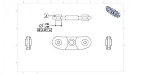
Hey guys I'm drawing a print and i wanted to convey to the guys on the floor (or me so i dont forget when running it) that i need the two posts on each side of this part to be positionally relative to each other. Ive attached a picture of how i currently have the print but im not sure if i have now created a much more complex part then it really is. The posts will all have bearings on them that sit above a convyer belt and assist gravity in holding it flat. So that being said what i am trying to accomplish is to make sure the bearings all touch the conveyor belt more or less. PLease tell me if im on the right track, thank you!........

GTOL1.jpg
 
Looks fine to me? The other alternative would be to just press in 2 shafts into the part but that tolerance is relatively easy.... Well depending on what they are making it with?
 
The only thing that introduces a problem is that you're identifying your datums on a centerline that goes through 3 diameters. Which one are they to be concentric to?

You'd be better off using a linear dimension for the diameter on one side, attach a Datum symbol to the dimension itself, making it clear WHICH centerline is the datum, and then the concentricity will be fine.

When identifying a centerline as a Datum you have to be careful. The centerline in your design is perfect, but it will not be, once made. There will be a centerline for the O.D. of the boss on each side, a centerline for the through-bore, and a centerline for the .680 radius of the plate.

ETA: This is the first google image result that describes what I'm talking about: http://help.solidworks.com/2011/Eng...g/wn_2011/Drawings-datum-lin-dim-centered.gif

Thank you! that is exactly what i was wondering if you could attach to the "side" of the post as opposed to the diameter of it. your theory makes 100% perfect sense.

dstryr: there being made out of t6061 but the problem is the thru hole is actually an m6 tapped thru hole, and i don't like trusting threaded holes for checking concentricity (maybe im crazy just a practice i have always stuck to).
 
Anyone who uses threaded holes for a datum that controls position should be shot.

In reality, they do make jo-plugs that will register on the actual pitch diameter and are supposed to give a precise, projected shaft above the hole that can be used to establish an 'accurate' centerline but I hate the premise.
 
Little problem with solid works and NX, that part views have no hidden lines by default. For the top view, there should be hidden lines showing the holes A and B, as wells as the central hole with the shallow bore.

I can't take one side or the other on the jury whether or not someone deserves to be shot, as there is an absence of evidence should their be a double hidden line in the upper view showing threads.


On another note, be carful of the number of decimals on "decretive" surfaces. For example the 2.875 and the R.438.
What dose the U.O.S chart say? the surfaces these refer to are not important from what I assume, but may have to be made and inspected to a finer dimension than the hole positioning. Chop off a few decimals or put a fraction size.

Many time I have had to make a kidney shaped piece of metal with a few holes punched in it. The hole location is often a few thou, the tolerance to one another is finer still, with diameter tolerance ranging from drill to ream quality. But the outside profile tolerance was +/-.001 or.0005 just because of carelessness in the UOS. I get on the phone with them, and revile that I can just band saws and belt sand the out side.

Ps. I just read the over statement concerning threads.
 
In NX, hidden lines are treated differently than thread lines. In a plan view, they'll show the "hidden" circle for threads even if hidden lines are off. In a side view, though, nothing shows if hidden lines are hid.

I don't like showing hidden lines. I only show them if it will help clear up something that might be confusing without 'em. I believe something in the ASME standards for drafting, it suggests the same. Not a rule, just a 'should do'. I'd have to find someone with a copy of Y14.100 to verify though.

Very good point on the tolerances... love getting a print and seeing every single number is .xxx precision... or worse, .xxxx. I hate the phone calls to get customer clarification on that...
 
Anyone who uses threaded holes for a datum that controls position should be shot.

Shot might be a bit harsh LOL but I agree with the thought.

To put things more in perspective the hole in a washer is always a good bit larger than the bolt diameter.

Any precise dimension from a threaded hole should be given from the hole before it is threaded. Of course then all dimensions from the threaded hole would have to be measured before the thread was cut. Seems a bit daft.
 
The part is poorly dimensioned and toleranced. The pictorial views are not even congruent. What are the two vertical lines crossing the .160 thickness symmetrically positioned on either side of Datums A and B? Please don't answer. Just fix the print.

Critical features are double dimensioned??? 2X Ø.472 TYP ???? Clue=delete TYP. Same feature dimensioned Ø.4724 . . in the plan view. WTF?

To your question: Define a plane as Datum A (the two faces of .472 bosses on one side of the part?). Define a .472 boss as Datum B. Tolerance boss opposite Datum B, True Position to A and B. Define the other .472 boss (on Datum A) as Datum C. Tolerance boss opposite Datum C, True Position to A and C.
 
Last edited:
OK. I'm missing something here.

Presuming that the part can rotate about the center axis (the middle hole)...

Why do you care where the bearings are, as long as they're within .1" or so?

Given that they're about the same distance from the axis of rotation, the two bearings will exert exactly the same pressure on the belt provided the assembly can rotate.

- Leigh

My take was that the part caries four bearings. Two on one side, two opposite. I think the concern is, when the part is flipped to machine the second side, that the Ø.472 bosses align (coaxial) on both sides.
 
I think the concern is, when the part is flipped to machine the second side, that the Ø.472 bosses align (coaxial) on both sides.
OK. Then simply define a concentric constraint between the two features.

It would be easier to measure that than to measure against a centerline that's floating in space.

- Leigh
 
For the people who commented about it being a jankey print.. Spend a day trying to decipher the prints from engineering at my work. I have literally spent a entire day picking them apart and going over them with whoever designed the tool because everything from the print to the solid model to the assembly conflicts and you cant tell whats really going on. Then they proceed to tell me " prints like this bad should never hit the floor." Well why do you let them then? With 7 full time people in the department you would think they could get it right. That looks nice compared to what I have seen. God I am glad to be moving on next Thursday!
 
I don't like showing hidden lines. I only show them if it will help clear up something that might be confusing without 'em.
Thank fully there is some leniency drawing standard. But I don't think that the enclosed holes make for the necessity to remove the hidden views.

sample drawing..JPG

Keep in mind that I Don't have the full drawing to work off of. These are just a few thoughts as how I would proceed.
-Datum A would be one of the bosses or one of the enclosed surfaces, which ever other components bear on.
-The central hole and the lower edge would make for good datums, as a dowel pin and a parallel bar could make for a consistent reference for both ends.
-
 
Last edited:
My take was that the part caries four bearings. Two on one side, two opposite. I think the concern is, when the part is flipped to machine the second side, that the Ø.472 bosses align (coaxial) on both sides.

This is the exact problem i was trying to avoid.
 
The part is poorly dimensioned and toleranced. The pictorial views are not even congruent. What are the two vertical lines crossing the .160 thickness symmetrically positioned on either side of Datums A and B? Please don't answer. Just fix the print.

Critical features are double dimensioned??? 2X Ø.472 TYP ???? Clue=delete TYP. Same feature dimensioned Ø.4724 . . in the plan view. WTF?

To your question: Define a plane as Datum A (the two faces of .472 bosses on one side of the part?). Define a .472 boss as Datum B. Tolerance boss opposite Datum B, True Position to A and B. Define the other .472 boss (on Datum A) as Datum C. Tolerance boss opposite Datum C, True Position to A and C.

Look i never said i was great at this, i told you i am a self taught guy and im trying to gather some info so i dont make the same mistake over and over, isnt that the point of asking for help? If i didnt give a crap about the print i gave to my guys i wouldnt even be on here asking for help so i could get some snotty answer like that from you. Thank you everyone else for your help. It looks like there a million ways to skin a cat here and to this day i wish there was a single "GTOL MASTER" that could just make a final decision on this kind of stuff. Like Jtek said i am constantly arguing with engineers about this kind of stuff. I actually had an engineer tell me the other day when i said his math was impossible on his print that, "what i was seeing was an illusion", i didnt think math was an illusion but welcome to the machining world.
 
maybe this purveys clearer what i am trying to accomplish...


assem.jpg

And heres the whole print if someone would like to toss it in paint and throw some lines on it for me, bc now i am really confused.....

BODY.jpg
 
It seems to me that calling out both center lines as datums relative to one another essentially makes the part impossible to inspect. The point of a datum is to establish a feature and then constrain a second feature to it in some specific relative relationship. By calling out datums A & B out to each other you are creating a chicken and egg scenario.

Another issue, as The real Leigh pointed out, is that the way you have your call outs constrains the features in a way that seems unnecessary. If I understand correctly you are trying to keep the bosses concentric on either side of the part, not necessarily to one another. This brings up a second point, in that concentric features by definition share a center line axis. If the center lines needed to be in the same plane then that would be parallelism and/or angularity, not concentricity.

I believe the way you would call out that feature to constrain it in the desired fashion would be like so:
Capture.JPG

More on concentricity here: Concentricity - GD&T Basics

Edit to add: Here's your print with said constraints. Other two bosses would be similarly called out with datum B on one side and the other side relative to datum B. If there was issues with a "kink" between the centerlines on either side than a run out, parallelism, angularity, or some other constraint might be required also.
Untitled.jpg
 
With size constrained via the diameter dimensions, a diametric true position would establish ideal control on the centerline. That's how you position two centerlines as in-line as possible.


Back
Top