What's new
What's new

10ee losing spindle speed

Jaymce

Aluminum
Joined
Jan 6, 2013
Location
New England
Hi all,
My 10ee stopped working a week ago. Will turn on and spindle would engage but slow down then stop.

Checked to see if I dropped a leg of 3 phase but it did not look like it (meter crapped out of course) and the bridgeport is running off the same cord with no problem.
While trying to diagnose spindle stopped altogether.

Pulled the plug on the machine and that is good as well.

I replaced the 2000 ohm capacitor today and cleaned all the rocker contacts.
Fired it up and it sounded good.

Made a few cuts and spindle speed began to slow after about 2 min of use.
I turned the machine off to assess. Opened the covers and turned the machine on, powers up ok. Then engaged the spindle with the lever and nothing.

I can hear 1 or both contacts engaging in the control panel but spindle does not spin nor do the belts.

Checked the "open" / "back gear" lever but that is engaged.

Any other help or tips would be appreciated. I did a search but came up with nothing but I may be using the wrong terminology in which case a nudge towards a thread would be helpful. Not sure if this is a common problem.

Thanks in advance for any help offered.

Jay

Sent from my SM-G950U using Tapatalk
 
Little more info.
I pulled the cover off the control box and tried again. The spindle has begun to turn again. I did notice that there is a fair amount of arcing on a couple of the contacts. Could this be causing a weak connection? Maybe I should order new or stiffer springs?

Sent from my SM-G950U using Tapatalk
 
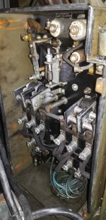
Please post photos of the inside of the DC control panel (the big box full of relays, next to the spindle motor) and the tailstock-end of the motor/generator (MG), assuming that's the type of drive that you have.

Cal
 
The DC panel looks OK, no obvious problems in that photo. Can you post a photo of the contacts that you're concerned about? Would you be able to get to the terminals at the bottom of the DC panel to make measurements?

I still want to see what the exciter end of the motor/generator looks like.

Cal
 
I will be watching this thread with interest. I have a 1950 with similar issues. It had had been left outside for several years and when I finally got it somewhat cleaned up and running it seemed to have the same problem as what Jay has described. I assumed my headstock bearings were going south and I dropped the ball and it's been mothballed since. It sure would be nice if an easier fix them the pricey bearings.

For what is worth the spindle never felt bad just seen to tighten up a bit. And over time I could start it up but same issue.

Hodge
 
Last edited:
The DC panel looks OK, no obvious problems in that photo. Can you post a photo of the contacts that you're concerned about? Would you be able to get to the terminals at the bottom of the DC panel to make measurements?

I still want to see what the exciter end of the motor/generator looks like.

Cal
The contacts I was concerned about were the ones that make contact when the forward/ reverse lever is engaged. They are the ones with the silver springs and cotter pins.

Cal in the box I pictured? Or elsewhere?


Sent from my SM-G950U using Tapatalk
 
The two big relays/contactors that are sitting side-by-side are the forward (F) and reverse (R) contactors. The relays at the top won't cause the symptom that your describing. Post a photo or two that show the contact surfaces of the F and R contactors.

The original motor/generator (MG) was located in the base, under the chip pan. I want to see what drive you have and if it's original. Take off the big cover on the tailstock end and shoot a picture of what's behind it.

Cal
I will do that.
I believe every thing is original. I will try and get pics in the AM but I usually do billing in the AM then head to a different shop for the day. Realistically it will be tomorrow PM or Friday before I can get those pics.
Thanks for all your help thus far.

Sent from my SM-G950U using Tapatalk
 
I have an early 50s square dial that came with MG set and DC drive.

Scrapped the whole electrical out and replaced it with 3 phase/VFD. So, I got parts for sale - cheap.
 
I may have multiple issues going on.

Machine started today
Made a few cuts with the rear cover off.
Machine was making an arcing sound.
Snapped a quick vid to upload but it was too big. Went to take a short vid and machine will not engage spindle.

Link to Facebook and you can see the arcing from the lower unit on the MG .

https://youtu.be/bNR_ttih-M4


Sent from my SM-G950U using Tapatalk
 
Will motor brushes also cause no spindle engagement?

Also is the lower the motor and upper the generator?

Sorry for what is probably simple questions. The manual I have does not show that end of the machine and is one I downloaded from online.


Sent from my SM-G950U using Tapatalk
 
I may have multiple issues going on.

Nah. Just the one.


Neglect.

Low need of maintenance is not the same as "zero".

No fear. Cheap enough to fix.

With power OFF, (disconnected and locked-out) get a demntal mirror, a camera on a "selfie-stick, or your handy-dandy automotive endoscope in to where you have sight of worn-out brushes.

- call or email Terri at Monarch with your serial number to order new ones.

You'll also want a NARROW "commutator stone". Grainger/Zoor have several:

Loose:

Buy Commutator Maintenance Products

Or mounted:

Made in USA Brush Seater & Commutator Cleaner Medium Grade BRSRX13MH - 48990733 - Penn Tool Co., Inc

Don't use these with the power ON! NO NEED!

As happens, there is an "A" section Vee-blot pulley on EACH OF the final-drive motor, and each of the exciter and main generator shafts.

Spin those, power-OFF still.. at a modest rate with anything you can get a vee-belt to. Salvaged warshing machine motor. Power drill.. whatever yah have.

Details on PM.

Just tellin' yah it is no big deal.

Tedious? Maybe.

But once put right it will last for YEARS again.
Awesome. Thanks, I'll call today.

Definitely lack of maintenance but honestly on the part of the last 75 years of ownership.

I might run this machine in a year what a machine shop would do in a week.

It should lead a fairly mundane and relaxing life from here on out.[emoji1787]


Sent from my SM-G950U using Tapatalk
 
This is a post from another Thread by CAL

icon1.png
Cal Posted


OK, the actual DC control of a motor/generator (MG) machine’s spindle motor is done by the tandem pair of Ohmite rheostats. What you’re calling the “DC Controller” is properly called the DC Control Panel. It’s nothing more than a bunch of relays and a few overload devices that perform functions like: turning the spindle motor on/off; reversing the spindle motor; preventing the operator from plug reversing it; dynamic braking; and handling acceleration under load (field acceleration). But the actual speed control is done by the rheostats.

The 10EE’s MG and rheostats are part of a Ward-Leonard drive system. In a Ward-Leonard drive, the drive motor operates in two regions: base speed and field weakening. Below base speed, the drive applies full voltage to the motor’s field windings and varies the armature voltage from zero (for zero speed) to full voltage, for the motor’s “base speed”, 690 RPM for a 10EE. In the field weakening region, the armature voltage is at maximum and the field voltage it reduced, causing the motor’s speed to increase well above base speed; a 10EE’s spindle motor with the field fully weakened will run at 2400 RPM (without load).

The Generator Rheostat (GR) is connected as a rheostat. Its windings are connected between E1 and E2 via contacts on the F or R relay. Depending on how it's set, terminal GF2 will have a voltage that varies from 0 to 115 VDC. The GR is specially wound so that its resistance only varies for half of its range. In the upper half of the speed control’s mechanical range the GR has zero resistance between GR1 and GF1, connecting the generator’s field directly to the exciter’s 115 VDC output. Note that the GR’s windings have voltage across them any time that the F or R relay is closed; they have a resistance of about 660 Ohms and dissipate about 20 Watts (hence its large size).

The GR controls the spindle motor’s armature voltage by controlling the voltage to the generator's shunt field. If either the F (forward) or R (reverse) relay is closed (i.e., the spindle is on), the exciter will put 115 VDC across the GR. The setting of the GR determines how much voltage appears at rheostat terminal GF2 and is provided to the generator's field. Below base speed, GR varies the generator’s field voltage causing the generator’s output voltage to increase (or decrease), thereby increasing (or decreasing) the voltage that is applied to the spindle motor's armature. At speeds above the spindle motor's base speed, the GR is in the section of windings that has zero resistance and it provides full voltage to the generator's field, which causes the generator to put out maximum voltage to the spindle motor's armature.

The other Ohmite rheostat, the Motor Rheostat (MR) also varies its resistance for only half of its travel. When the speed control is in the field weakening (higher speed) range, the MR is in a section of its windings where its resistance varies. The MR is connected in series with the spindle motor's field. As you increase the speed control above base speed, the MR increases the series resistance, reducing the voltage to the spindle motor's field (weakening the field) and causing the motor's speed to increase. At maximum speed, the voltage across the spindle motor's field drops to about 40 VDC. During the entire time that the MR's resistance is increasing, the GR is in the zero resistance section. Similarly (in the base speed region), when the GR’s resistance is changing, the MR is in a zero resistance region, applying full field to the spindle motor.

The MR is always connected in series with the exciter and the spindle motor’s field, even when the spindle is off. When the spindle is off, the DC control panel connects the braking resistors across the armature. If you then try to move the spindle, the spindle motor acts like a generator and can be very difficult to turn if in back gear, since rotating the spindle causes the motor to generate voltage that is fed to the braking resistors.

I hope the above helps you understand what’s going on.

As far as checking out the MG and spindle motor without the DC control panel, it’s actually relatively simple; you just need to make a few connections between the terminal panel on the MG, the Ohmite rheotats and the spindle motor. First, rig up a switch and fuse to connect the GR to MG and control the generator’s field; you need a 1 Amp fuse wired in series with the switch.

Connect the GR to the MG, as follows:


  • GR terminal E2 to MG terminal E2
  • GR terminal GR1 to switch and 1 Amp fuse, then to MG terminal E1
  • GR terminal GF2 to MG terminal GF2


Connect the MR to the MG and spindle motor’s field, as follows:


  • MR terminal E1-2 to MG terminal E1 via a 2 Amp fuse
  • MR terminal F2 to spindle motor terminal F2
  • Spindle motor terminal F1 to MG terminal E2


Connect the MG to the spindle motor’s armature, as follows:


  • Spindle motor terminal A1 to MG terminal GS1 via a 15 Amp fuse
  • Spindle motor terminal A2 to MG terminal GA2


The fuses are in case you hook something up wrong. Obviously, all this wiring is done with the machine powered off and disconnected from power.

With the MG running and the speed control set to minimum (counter clockwise), close the switch. The spindle motor should run slowly. Adjusting the speed control clockwise should take the spindle motor from minimum speed to maximum, through both the base and field weakening regions of operation.

Cal

10EE smoking and arcing (practicalmachinist.com)


Back
Top