What's new
What's new

1940 10EE saddle oil lines

rimcanyon

Diamond
Joined
Sep 28, 2002
Location
Salinas, CA USA
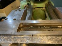
I’m in the midst of an overhaul of the 1940 10EE ( will post more in a separate thread). I have the saddle off and have a couple questions about the lubrication system. First, which metering valve controls the front v-way? Its either the first or second, since those are the ones that go forward. Here are some pictures:

EB012B9B-D116-4DFC-8E3C-D77A142A9589.jpg38EF09AA-7223-4F15-8231-7F72E63152CE.jpg

Second, when did Monarch add lubrication lines for the feed clutch bushings? Did it happen on Round Dials or only on Square Dials? It may be hard to see from the photo, but both of the oil points for the feed clutches are dry. Maybe Monarch thought they would get some splash, but that is not what is happening.

972F57C0-F41A-49B0-806A-000B57831CE8.jpg
 
Answered my own question: the second oil line from the front feeds the v-way. The line itself was nice and full-flowing, so I will order some MJB-00 metering valves. Might as well replace them all while its apart.

I’d still like to know when the separate lines from the upper apron sump were added for the feed clutch bushings. I could always drill some more holes in the upper sump and add my own copper lines angled to do the job. If anyone has a round dial with such a setup, please post a photo.
 
What month was this 1940 10ee produced? Is it MG powered? or is it the Sundstrand? Hydraulic drive lathe?

I'll try to remember to look at the apron from my 'parts' 10ee, and see if it has the apron copper lines for the feed clutches.
If so I will take some hopefully helpful photos..

I'm 99% sure that my 11/41 production Round Dial 10ee has the oil drip lines to the feed clutches. But that lathe is together and in use.
The 'parts' lathe is a mid 1942 production, so I'm pretty sure it will have those drip lines..

I'll hopefully be able to post a photo or two tomorrow.

DualValve
 
What month was this 1940 10ee produced? Is it MG powered? or is it the Sundstrand? Hydraulic drive lathe?

All I remember is early 1940. I’ve had it 26 years now, it was the first machine tool I purchased over the internet, from Anchor Machinery in Port Orford, OR. It has a Sundstrand hydraulic drive. The only part that is not original is the motor, which was a 440V 3-phase motor. I replaced it with a GE 3HP single phase motor, which is perfectly suited to the machine.

I had the metering units cooking in the ultrasonic cleaner all night, so I will test them and see if they have a good flow, then put them back in service.j. The front v-way was only getting about 1/10 as much oil as the rest were producing, so I’m hoping the cleaning solved that problem.

Once the saddle is sorted, I plan to remove the apron and clean the oil sump and replace the pump filters. Since the apron and saddle will both be off, it would be a good time to scrape the green paint off and see what is left of the original dark blue grey. I started the overhaul at the beginning of January, so a lot has already been done (alignment checked, cross slide scraped flat and perpendicular to the spindle, DRO fitted including milling a flat spot on the saddle where the reader head gets mounted, wipers replaced, oil grooves cut in the cross slide, underside of cross slide relieved .010”, gib fitted with a .007” shim epoxied to the back, ...). Other than cosmetics, the only thing left to address is the tailstock quill. My plan is to get it hard chromed then hone the bore to fit, then scrape the bottom and shim between the top and bottom, so there is some work. One other thing I am considering doing is replacing the taper attachment with one from a later lathe. They changed the taper attachment design in 1941, and the later design has one advantage: you can fit a long cross slide to the machine. The early design gets in the way. I have a later cross slide (from a 1942 machine) that has the rear toolpost. That’s a nice option to have, but the primary motivation is that the sliding surface is 4 or 5” longer, just like the later lathes. I’ve already scraped and fitted both cross slides, its just a matter of should I keep the machine original, or not.
 
I took some photos of the mostly-stripped apron from this 4/1942 Round Dial.

View attachment 277243

Hopefully the photos will show enough for you to maybe add oil lines to your apron if it does not have any.

First: the tailstock end of the apron with the supply line from the pump entering the middle of the Tee. The bottom fitting goes to the supply line that fills the lube-supply basin in the top of the apron

ApronEnd.jpg


The top of the Apron showing the lube basin where the oil drip lines originate. This basin had a piece of felt in it, and you can see the notch that is a 'overflow' return to the apron's sump.

277245d1580531020-1940-10ee-saddle-oil-lines-apronlubebasin.jpg


Supply lines from the basin: two to the feed clutches, one to the brass gear driven by the feed rod worm gear.

277245d1580531020-1940-10ee-saddle-oil-lines-apronlubebasin.jpg


A view from the bottom of the apron, showing the pump's supply line.

277247d1580531572-1940-10ee-saddle-oil-lines-apronbottom.jpg

Hopefully your 2-year older Apron casting has the cast-in basin that could be drilled and have lines swaged into it to distribute the lubricant.

DualValve
 
Last edited by a moderator:
Well for some reason I cannot post inline images..

Here is the second image, the top of the apron showing the lube basin

ApronLubeBasin.jpg


DualValve
 
Third image, The lubricant supply basin with the drip lines. Two going to the inside of the apron to lube the two feed clutches.
One going outside down the back of the apron to lubricate the feed worm gear and driven brass gear.

ApronTopLines.jpg

DualValve
 
Third image, The lubricant supply basin with the drip lines. Two going to the inside of the apron to lube the two feed clutches.
One going outside down the back of the apron to lubricate the feed worm gear and driven brass gear.

View attachment 277246

DualValve
Thanks for posting the photos, DualValve. Very interesting. The 1940’s top sump has the same holes (1 &2 in the photo below). They also have the weir (3) that supplies the gear train. What’s different is how the copper tubing is run. The 1940 has a line to the idler shaft’s bearing, and the hole adjacent to it is empty. I think I will use it to run a line to the longitudinal feed clutch, since I use that all the time, and leave the cross feed clutch as is, since I rarely use it. I don’t really want to disconnect the line to the idler shaft bearing, but I am curious why Monarch got rid of it in later round dial lathes.

3D29901C-BE88-4B85-BC9E-28842F29214E.jpg
 
RimCanyon: Is it possible that the copper line feeding the idler is bent wrong, and actually should be dripping on the feed clutch?

I think the most important lube line is the one that goes down the back of the apron and drips on the feed-rod worm gear and it's driven brass gear.. They have no other source of lubricaton.
The gears in the apron do a fair amount of picking up and slinging oil around when the feed is being used.

DualValve


Back
Top