What's new
What's new

1942 10ee power questions

TexasDan

Plastic
Joined
Jan 29, 2019
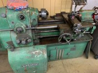
Just bought a 1942 Round dial Monarch 10ee and I’m quite excited to get it powered up. I’m new to the lathe world so please forgive me if I sound stupid. Soo here it goes.

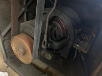
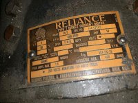
The motor is a 3hp reliance 230v armature 115v field. I however don’t know what that means. First question. Is it 3 phase?

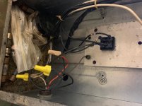
After searching the internet and this forum I’m even more confused because in addition to the motor not specifying it’s phase I also have an extra box on mine. You’ll have to look at the photos for more info. Is it part of it a phase converter?

The power chord has 4 wires. Didn’t get a photo of that but nothing is marked on the chord or the box.

Any help is appreciated.

Thanks for letting me be a part of the forum. I look forward to making some new friends and learning a few tricks :-)
IMG_0973.jpgIMG_0976.jpgIMG_0978.jpgIMG_0977.jpgIMG_0983.jpg
 
Last edited:
That's not a standard drive, someone's changed out the original. get some better pictures of the inside of the new box and what's feeding it as well as what's in the bed under the tailstock and some folks may be able to take a guess.
 
The Motor that you have is 0 phase in other words it runs of of DC volts. Your lathe used to be a MG unit to convert the 3 phase power to DC. The box you have is a home made thing to convert the AC to DC (rather crude) it uses variable transformers and solid state rectifiers to get the dc for the motor and field for the motor.
 
Wow

I'm not sure that control is gonna work, but it appears to be:

One rectifier 230 volts to armature, variable with top control
One rectifier 120 volts to field, adjustable for field weakening for higher top speed by lower control


The reason it says not to touch the bottom one is it will result in runaway unless used with some intelligence

Single phase anyway

a bit scary
 
The two square things on the left of picture 5 are full wave bridge rectifiers, the round disk with holes in it in the middle is definitely a Variac, the round thing on the right probably is also a Variac. Presumably one on the right controls the armature and the other one, marked "do not touch" controls the field. It appears to be set about the midpoint so it probably supplies the 120 volts for the field. That implies that it is set up for 240 volt single phase operation. This is typical of the kluges people make when they don't know how to maintain the original motor generator. If you take the headstock end lower cover off and send us a picture of the control panel, we can make a guess as to how much of the control system is left.

Bill

Between starting this post and finishing I got a long phone call. Several posted during it so I am a little redundant. I agree with the interim posters.
 
Gawd I didn't even think of the original control being still in there. Maybe is the motor generator still in under the tailstock end?

If that was still there, probably worth fixing with the knowledge available here
 
Dan!...

+1 The motor, gearbox, belt... that's all original...

The power control stuff is all home-made.

Here's how it works:

The DC motor has two circuits- first is a field circuit... it establishes a magnetic field that the armature rotates within. The second, is the armature, which is fed by a commutator, which switches polarity to make the motor armature turn.

If you went to grade school before 1980, you had basic electricity in science class, and used a horseshoe magnet, a couple nails, some wire, a cork, and some hairpins to make a permanent magnet DC motor... same thing here, but the permanent magnet is not permanent, it's a field.

So 10EE's M-G drive system has TWO power circuits... one that provides variable voltage for the field, and another that provides variable voltage for the armature. Changing polarity of either (but not both) reverses the direction of the motor.

Originally... your machine had a motor-generator in the belly, occupying the space from the back side of the spindle motor, to the end under the tailstock cover. The motor generator had a constant-speed 3-phase AC motor driving a pair of DC generators- one for the field, another for the armature. Each of these generators had a DC field which was modulated by a two-piece potentiometer chain-driven off the speed control knob. The system is frequently referred to as "Ward-Leonard", and it has a very stable and robust operating style.

What your previous owner did, was replace the motor-generator unit and a pinball-machine's worth of relays and contactors with a pair of variable transformers (Variacs), and rectify the output of those variacs into DC for the field, and DC for the armature.

It's clever and compact... but probably not able to equal the original setup in performance or durability. PROBABLY okay for a home shop and small parts work. I'd use it, but then again, I'm certain I could fix it... because I could reverse-engineer it while sitting on the toilet eating a bowl of chili.

This runs on single-phase. If you can figure out where the guy brought in his single-phase power to those variacs, follow it backwards to the main input switch or contactor. The most problematic issue, will be if he left remants of the old system in there, as that would generate confusion.

But they probably didn't include anti-plugging, dynamic braking, or other features that make it really nice.
 
Oh, and the top knob is probably for armature (the 200v variac), while the lower "DO NOT TOUCH" is probably for field.

F/R probably reverses polarity of the FIELD, while the top switch shuts off power to both variacs.

- Aside note- the DO NOT TOUCH variac, if it controls only the field, will need to be backed off when you get to higher spindle speeds... as a DC motor's armature will reach a speed where the field actually LIMITs the spindle speed... backing off the field voltage will allow the motor to spin faster. Doing so, with this controller, means your speed control is a two handed ordeal.

The other issue I see (and I would address it if it were in my shop) is that the control box requires you to reach more-or-less over a swinging workpiece and snag your tie while adjusting the speed. Always wear clip-on ties when working with this machine. ;-)
 
Dave, you are probably correct that one switch reverses the field. This motor probably has series field coils, in which case reversing the field will degrade speed stability. It probably doesn't matter that much in reverse, though. I asked to see if the contactor panel was still there, but it seems unlikely.

I had a South Bend lathe that had the switch on a pipe directly above the work. Exciting when something came loose and was flailing around. When I converted it to a DC magamp control, I put the control box on the tail end where I would probably be ducking in an emergency. Really hated that damned switch.

Bill
 
Dan,

What's the serial and build date from the plate on the base, in front, below the tailstock?

Dave and Bill have pretty well covered what you have, but I have a few things to add. First, there's no reason that what you have won't work just fine for you, once you understand how to use it. The pair of variable transformers that were used are not cheap; this is not an amateur conversion and appears to have been someone who knew what they were doing.

I agree that the lower knob controls the spindle motor's field. The original control system varies the field voltage from 115 Volts DC down to about 40 VDC. Without seeing how everything is wired, it's very possible that the lower transformer is wired to vary the field voltage from 0 to 240 VDC. If that's the case and the operator turns it all the way up, he could damage the motor; which could explain the "Do Not Touch" label. If you know not to turn it above 50%, you're fine and I suspect that the person who did this and/or the original operator(s) understood that. Also, if you turn the lower transformer too low (below 40 VDC) the motor will over speed; a second reason for the "Do Not Touch" label. (Assuming that I'm right) both problems could be handled by stops limiting the travel of the lower transformer.

Another thing that the operator needs to understand about the two knobs is that the upper knob (the armature voltage control) needs to be at maximum before the field is reduced. All of these things were taken care of by the original control system. If it was my machine, I would use it as is, after understanding exactly how it's wired.

The 4-wire cord that you have is designed to bring in both "hot" legs of a 240 VAC single phase circuit (the red and black wires), the ground-potential "neutral" wire (white wire), and the safety ground wire (bare copper wire). Both 120 and 240 VAC are available inside the chassis and it just depends on how they were used. You need a four wire service for it, just like some electric clothes dryers use. Can you post a photo of the plug?

Your next step should be to trace out and diagram the wiring in the box containing the variable transformers. Once we see a diagram we'll be better able to help you with what you've got.

Cal
 
Wow. Thanks for all the feedback :-)

As requested here is a photo from under the tailstock.

Unfortunately there is no plug just exposed wires.

I had expected to find a control board and wires but clearly someone has gutted this old girl.

I’ll definitely not touch anything inside the box. Thanks for that bit of info.

Serial number is: EE17139

Let me know if there is any other info that will help. After reading a bit I think it’s safe to say it’s 220v single phase. I just wanted to be absolutely sure before I powered it up.

Again thanks to everyone. I’m sure more questions are sure to come and of course if you have a doubt about the wiring please let me know. I’ll be running power to it this weekend.

Dan


0D45ED65-CDAC-4CFD-AC22-A172A0B3F729.jpgCB4D796C-D7D3-49D9-9333-9009175BBAD7.jpg1E2850CC-E92E-445F-B951-C9B379FF9521.jpg990AB6C1-AF29-4AB0-A779-CF266991E5B2.jpg
 
The original drive system is gone, with the exception of the DC spindle motor. The machine originally had a piggyback-type motor/generator (MG), mounted in the empty space under the chip pan, which provided DC voltage for the spindle motor's armature and field. The MG was controlled by a DC control panel, containing relays, plus a large pair of rheostats. The DC control panel and the rheostats were located next to the spindle motor, under the headstock. There would have also been an AC contactor, located under a cast iron cover on the back of the headstock. The cover is at the bottom of and behind the transformer box.

By the way, your style of machine is know as a "round-dial" 10EE, the name coming from the round dial on the quick change gearbox.

To hook this up, have your electrician install a NEMA 14-30 outlet and plug or cord like these: NEMA 14-30R outlet, NEMA 14-30P cord.

Cal
 
Thank you again to everyone who helped. Got er powered up and soon I'll start my first lathe project.


Back
Top