What's new
What's new

1962 10EE Headstock help needed

AlfaGTA

Diamond
Joined
Dec 13, 2002
Location
Benicia California USA
I own a 62'EE that has been apart in my garage for years.
I started out doing a full restoration years back. Have had the bed reground (Schaffer) the carriage and cross turcited and scraped.
New class 7 (Franfer) spindle bearings along with a pair of angular contact bearings fro the end of the spindle....

Some questions: I have the Monarch CD and within is a section of the headstock, but ii is a single oil sight glass unit and mine has three.
The internals are a bit different.....
In specific the oil "slinger" at the rear of the rear spindle bearing.....

attachment.php


attachment.php


The question is which direction should this point? And what locates it in the housing...Is the outer just biased against the face of the rear bearing or?

Also, i seem to be missing the drive fro the mechanical tach....appears to be a square drive coupled to a blade , but i am not sure...anyone who could provide a sketch would be appreciated.

attachment.php


On the shaft that shifts the dog clutches for threading (EE2889), the rear end is grooved to allow oil to escape when it moves, should the groove be positioned up or down...?

Finally (for now) the rear spindle bearing on my machine was a double row , and i am replacing it with two precision angular contact bearings. (721OCTRDVLP4) should the bearings be
fit with the thrust side facing away from each other or facing each other?
Are the rear bearings setup with axial clearance in the housing and end cover to allow fro thermal expansion of the spindle?
Is there anything to know about the rear slinger, will the original setup work with the different bearing setup....anyone been here before?

Anyone have a good copy of the three glass head stock sections would be a great help...

Is the thickness of the gasket for the front of the spindle cover critical...anyone know the thickness of the original?
Does anyone use sealer with the gasket" perhaps something thin like aviation formula "Permaterx" or "Wellseal"?

Thanks in advance, all help greatly appreciated.
Cheers Ross
 
Last edited by a moderator:
Dog clutch shaft: there is a collar with a flat on the front of the shaft to mate with the interlock. The collar should only have one position on the shaft so it sets the position of the shaft.

The Monarch gasket was on the order of 0.020". No sealant here, but a little Halomar can't hurt.

The bearings are squeezed by the inner race. Think about that when assembling. *The inner races hold the outer races inward* said another way.

Here is the slinger picture and the rear bearing picture.

Here is my bearing install info.

"new" spindle/ new bearings, 10EE WIAD old style rear bearing headstock

Edit, realized was asking about the rear bearing orientation, added picture.
 

Attachments

  • IMG_1131.jpg
    IMG_1131.jpg
    9.3 KB · Views: 56
  • IMG_1132.jpg
    IMG_1132.jpg
    12.1 KB · Views: 54
Thanks for the response.
Bit confused by your statement on the shaft orientation....Likely we are not describing the same part....
Mine does not have any collar with flats.
My problem is the shaft with the square center section (top drawing Part # EE 2889) Mine was disassembled and one can bolt it together in one of two orientations ..
There is a groove in the shaft portion to the left of the square. There to relieve the oil from locking the movement as the end is plugged.(hydraulic lock)

The question although i would guess not critical is which way to fit the clearance groove...at the top (12:00) or at the bottom (6:00)
At the top it will hold oil , but could cause it to be more difficult to move...at bottom the oil will drain, less lube for the bushing....

The install marks from the fork seem to point to the notch being up at least the last time it was installed....any thoughts.

attachment.php


Cheers Ross
 
I own a 62'EE that has been apart in my garage for years.
I started out doing a full restoration years back. Have had the bed reground (Schaffer) the carriage and cross turcited and scraped.
New class 7 (Franfer) spindle bearings along with a pair of angular contact bearings fro the end of the spindle....

Some questions: I have the Monarch CD and within is a section of the headstock, but ii is a single oil sight glass unit and mine has three.
The internals are a bit different.....
In specific the oil "slinger" at the rear of the rear spindle bearing.....

The question is which direction should this point? And what locates it in the housing...Is the outer just biased against the face of the rear bearing or?

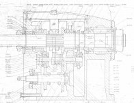
Ross, here is a drawing that may help Cal sent me this drawing, it is an early square dial headstock.

headstock.jpg

The outer part of the oil slinger is a light press fit in the headstock, in the back of the front bearing bore. The inner part gets installed on the spindle between the bearings and the locknut. The axial clearance between the outer and inner part needs to be correct; i.e. on my lathe, the part that was pressed into the bearing bore needed to be about .050" proud of the bore. If it had been pressed in as far as is shown in the drawing above, the parts would have rubbed. I used a depth mic to verify that there was about .005" clearance.

Also, i seem to be missing the drive fro the mechanical tach....appears to be a square drive coupled to a blade , but i am not sure...anyone who could provide a sketch would be appreciated.
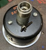
Here is a photo that shows the part:

IMG_1020.jpg

I have an extra, send me your mailing address.

On the shaft that shifts the dog clutches for threading (EE2889), the rear end is grooved to allow oil to escape when it moves, should the groove be positioned up or down...?

The groove goes down. I think it provides better flushing action that way.

Also, if the groove was up, wouldn't that tend to collect oil in the space between the shaft and the plug, inside the bushing? Might cause some difficulty shifting into reverse.

Finally (for now) the rear spindle bearing on my machine was a double row , and i am replacing it with two precision angular contact bearings. (721OCTRDVLP4) should the bearings be
fit with the thrust side facing away from each other or facing each other?
Are the rear bearings setup with axial clearance in the housing and end cover to allow fro thermal expansion of the spindle?
Is there anything to know about the rear slinger, will the original setup work with the different bearing setup....anyone been here before?
The question has come up before, but I have never seen an answer posted. You might want to duplicate the later rear oil slinger if you can get ahold of an example or some measurements.

On the Vintage Machinery site there is a mid 60's manual posted that has some drawings at the end that you might find useful. They show the angular contact bearing setup.

Monarch Machine Tool Co. - Publication Reprints | VintageMachinery.org

Monarch Machine Tool Co. - Publication Reprints - Model 10EE Manual | VintageMachinery.org


Anyone have a good copy of the three glass head stock sections would be a great help...

Is the thickness of the gasket for the front of the spindle cover critical...anyone know the thickness of the original?
Does anyone use sealer with the gasket" perhaps something thin like aviation formula "Permaterx" or "Wellseal"?
I just bought mine from Monarch. No sealer needed, just make sure the gasket has a hole for the oil slinger return passage.

Also, the gasket for the rear oil slinger/cover plate may need to be adjusted for thickness to prevent the oil slinger from rubbing on the rear plate. On my 59 there were two gaskets in there. However, when I installed the plate only one was needed. What I did was to first install the rear plate and oil slinger without the gasket, which seated the bearing.

Thanks in advance, all help greatly appreciated.
Cheers Ross
 
Ross, just curious, did your original double row rear spindle bearing have a hole thru the outer race? I had a conversation with Rimcanyon about this, and I distinctly remembered ( or not) that the third sight glass indicated the level of a channel in which the bearing straddles, with the hole(bearing) mounted 6:00 so to pick up oil from this channel. Rimcanyon said on his that the bearing never straddled the channel. The print above confirms this, but makes no sense if the bearing has a hole in the bottom. I figured they (Monarch) decided that the holy rear bearing setup and channel was more trouble than it was worth, the bearing was getting lubed from splash, and did away with the design. I know the oil level on mine in that third sight glass leaks out very quickly, I guess it goes into the main chamber. I replaced that bearing with a double row as original but without the hole as it was NLA and started not to keep oil in it as I considered it superfluous...
 
Ross, just curious, did your original double row rear spindle bearing have a hole thru the outer race? I had a conversation with Rimcanyon about this, and I distinctly remembered ( or not) that the third sight glass indicated the level of a channel in which the bearing straddles, with the hole(bearing) mounted 6:00 so to pick up oil from this channel. Rimcanyon said on his that the bearing never straddled the channel. The print above confirms this, but makes no sense if the bearing has a hole in the bottom. I figured they (Monarch) decided that the holy rear bearing setup and channel was more trouble than it was worth, the bearing was getting lubed from splash, and did away with the design. I know the oil level on mine in that third sight glass leaks out very quickly, I guess it goes into the main chamber. I replaced that bearing with a double row as original but without the hole as it was NLA and started not to keep oil in it as I considered it superfluous...

That bearing is lubricated by splash also. The oil trough above it feeds it.
 
Small additional question regarding teh tachometer....
Is there a seal on the drive to keep oil out of the tach....

Got a copy of the manual PDF (thanks Colt45) and the drawing is a bit fuzzy there, but looks like something between the tach and the casting that supports the drive gearing...
Looks like it might be EE 1081

attachment.php

Cheers ross
 
Ross,
part #546-1 is the only seal I am aware of, and it just seals the outside of the tach so no oil gets into the tach compartment. If there is an internal seal inside the tach itself I have not had it that far apart.

There is also a cork gasket, EE1079, and not shown, there are 4 gaskets between the glass and the body of the tach. If you remove the bezel to clean the glass, on the inside, you can also remove the tach assembly from the case and add a few drops of oil to the felt wick that lubricates the tach shaft.
 
If the original double row rear bearing is replaced with a pair of angular contacts, How does one preload them?

The later spindles are threaded at the end and a small pulley for the feed belt was added between the nut and large spindle pulley, so there is positive contact all the way to the bearing.
 
Thank you for that info. This is for a UK built CVA lathe, 10EE but for the gearbox. No drive issues here.

I would like to use a roller bearing here, but they all have significant clearance. Apart from the types that have a tapered bore to jack the clearance and preload.
 
Back from skiing, Alfa, Sorry about the shaft, Thought you were asking about the shaft with the gear that you control the sliding fork with, not the shaft that the siding fork rides on. RC did clear it up.

I also missed that you were changing the rear bearing from the 5210 double row to a pair. I discussed this in

10EE Spindle removal and bearing reinstallation - older style - New Departure cat

You'll have to make a new end cap, etc for the wider angular pair as mentioned in the thread above.

5210/5510s are still available:

5210(MAX) New Departure New Double Row Ball Bearing | eBay

I think the "max" refers to to maximum ball compliment with the filling notch. I used the bearing above, as described in this link.

10EE spindle rear bearing replacement study, old style double row angular
 
If the original double row rear bearing is replaced with a pair of angular contacts, How does one preload them?

Single row AC bearing preload is established by precision ground spacers that reside between the inner and outer races of the pair to "match them" as in the case of the right end of the ee spindle. When there are no spacers the inner and outer races are precision ground to establish the preload and "match" them....I believe in this case they are called a "universal" AC bearing set. There are volumes of information written about this topic. Generally speaking if the spacers or bearing races are properly matched you run the retaining nut up as tight as you can practically get it and the matching done with the races/spacers does the rest. The double row bearing clearance at the left end of the tail stock would be established at the bearing MFG....nothing you can do with it in the field. Based on what I see in the drawing there is no way to preload a pair of single row AC bearings on the left end of the spindle.
 
The double row bearing clearance at the left end of the tail stock would be established at the bearing MFG....nothing you can do with it in the field. Based on what I see in the drawing there is no way to preload a pair of single row AC bearings on the left end of the spindle.

For my money don't believe you want to preload the end bearings in the spindle....The inner races are indeed crowded together from the end of the spindle through the main drive pulley and feed drive pulley.....
But think one would want clearance on the end of either style bearing that was fitted to allow for thermal growth of the spindle under use. That spindle is going to grow more than the iron surrounding it, better have
somewhere for it to go.....
Cheers Ross

You are absolutely right, the left end bearings/spindle need to float. They are obviously held at the right end. Looks to me based on the drawing the float comes from the outer race "floating" in the head stock casting. Any arrangement for the left end bearings needs to allow for that. It could be the spindle is floating in the inner race. I can't be certain.
 
The OD of the rear spindle bearing(5210)/or angular pair, is a slip fit in the casting. The id is captured by the lockring at the tail end of the spindle through the pulley stack. When I say slip fit, it is like one micron of slip worth. Very easy to get the rear bearing stuck in the casting with the slightest misalignment.
 
The OD of the rear spindle bearing(5210)/or angular pair, is a slip fit in the casting. The id is captured by the lockring at the tail end of the spindle through the pulley stack. When I say slip fit, it is like one micron of slip worth. Very easy to get the rear bearing stuck in the casting with the slightest misalignment.

Makes perfect sense to me and well inline with what I was thinking and NEEDED to be. I don't see a snap ring illustrated in the drawing rimcanyon shared so I was assuming there was a setscrew in EE2614 (which appears to be a slinger) that held the bearing there. The other possibility I thought was the set screw on EE2302 that retained that stack up. In the end I don't think it would take too much to keep that bearing near home as there should not be too much pushing it around.

In the end though, from what I see illustrated in the drawing there is minimal hope to replace the 5210 AC pair with two single row AC bearings. Someone did suggest there was a retaining nut to hold on a sleeve and other "stuff" on different versions of the spindle that might allow for that, but not in the design iteration in the drawing shared earlier.
 
You could change the bearing to an AC pair, but you would have to make a new bearing cap, new spindle lock disc, new this, new that... or get pieces from a later model lathe. In any event, with my new Fanfnor (Fafnir) fronts and the 5210 rear I got about 20 millionths runout, so the 5210 or 5510 from Locate BB is good enough.

edit: did I really write Fanfnor??? My other hobby, Italian wine, is showing again...
 
Last edited:


Back
Top