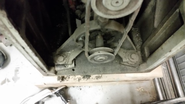
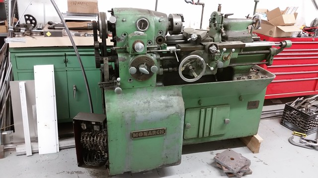
I looked today and I can't find holes to bolt it down. I assume I'll want leveling feet on this at some point as well. What am I missing?
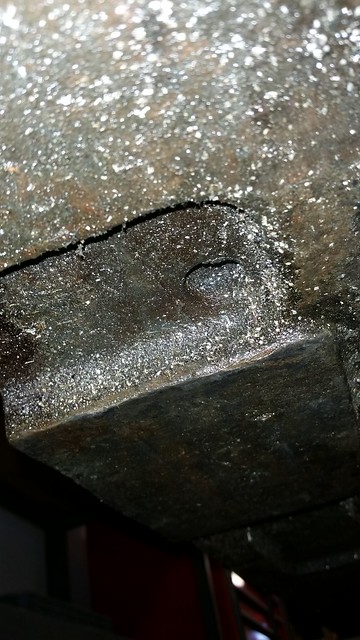
One pad, TS end offset toward OVERALL, not local, centre-mass (front).
Two flat pads, HS end. All three have nominal 5/8" casting-cored holes.
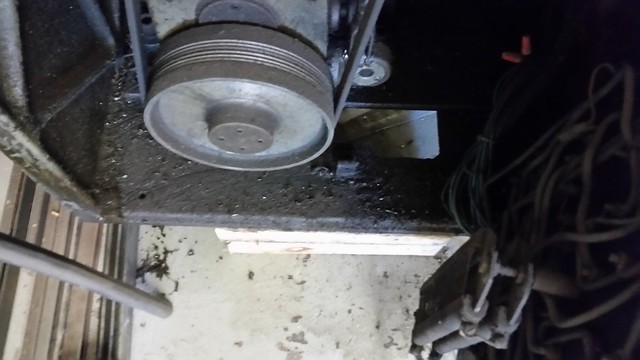
One at HS may come up right at the rear side HS end of the motor mounting plate. I moved it/made a new hole only slightly different location to clear the plate.
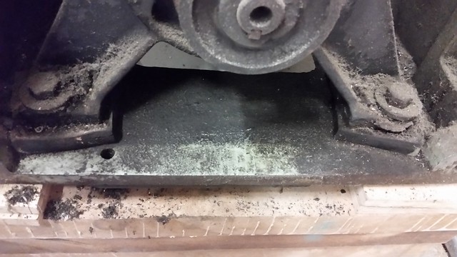
Being as-cast holes, they are tapered. I used-up a Silver & Deming drill, (grabbed and BENT..) plus one to overbore my three to a uniform 3/4".
At each point, a 3/4" bolt, hex head DOWN, protrudes through a Northern Tool 3300 lb rated 8-bearings-as-wheels skate.
The topside gap in the C-channel body is fitted with a linen-bakelite plate. Several heavy washers and a pair of jam nuts allow letting the weight rest on the skates, ELSE see the head of the bolt jacked down onto the top of a separately emplaced steel "scotch" block positioned between the axles.
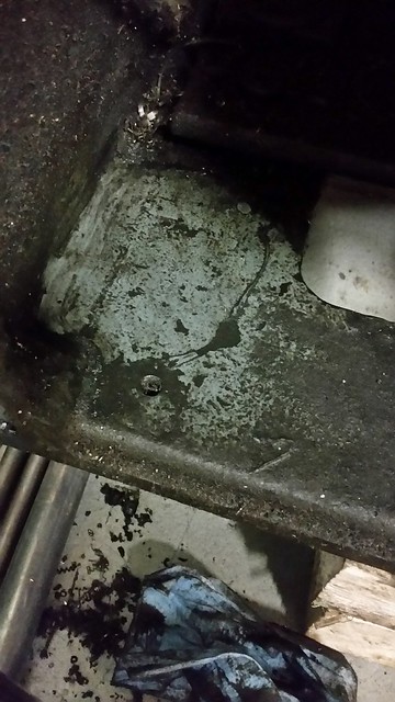
When I need to move the 10EE, change angle, or rotate it in its own length, I "pre-aim" the skates by short lift with a garage mechanic's trolley/floor jack. Or my 'toe' jacks.
Works for me.
That 10EE had arrived here, same holes used for through-bolts to a stout 2" dimensional, not 2" nominal pallet.
I cannot recommend lag screws. Present-day "farmed" timber is too coarsely-grained, so they split easily. Carriage bolts or machine bolts, and good washers, rather.
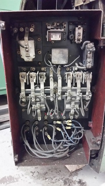
 20171221_111927
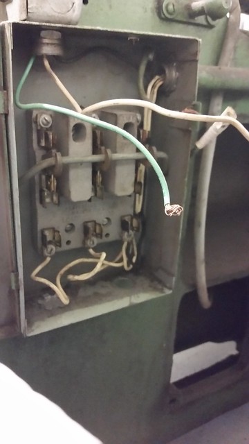
  20171221_111533
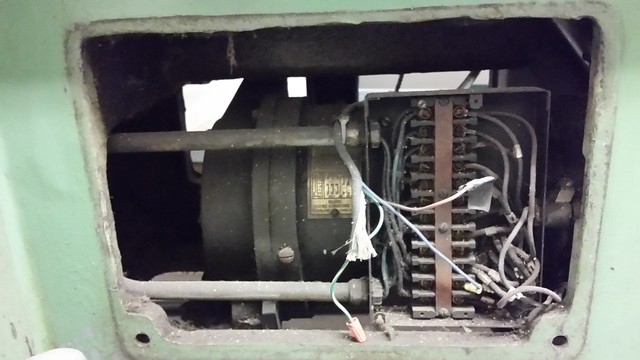
  20171221_111900
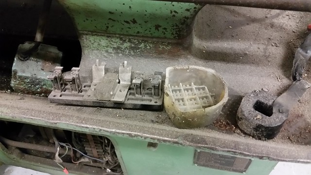