rabler
Cast Iron
- Joined
- May 25, 2020
- Location
- Rural S.W. Indiana
I finally got started on cleaning up the 10EE.
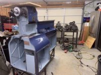
Got it stripped down, electronics, motor, transformer cabinet, coolant pump, carriage, apron and gearbox removed. Headstock stays on. Primed and painted the body yesterday and today. It is sitting about 16” above normal, I raised it up to make it easier to work in the lower part of the base.

Wanted to get that started to give the enamel plenty of time to harden before scratching it up reassembling. It will take me a while to go through the apron and carriage. Carriage, apron, etc are on the table behind and to the right of the lathe. I’m hoping the gearbox will be OK with a good flush and clean without disassembly. I expect the carriage will end up getting Rulon but haven’t crossed that bridge yet.
This one has a 5hp DC motor with back gear. It came with aDanfuss DC controller and would only turn about 1000rpm, suggesting that there was no field weakening circuit. Rather than troubleshooting that, I’m going with a Parker/Eurotherm 514/507 per some older threads on here. It’ll get tested out on the bench before going into the lathe. Unfortunately the main transformer, T5, leads are brittle and corroded so won’t be able to use that.

I’ve decided to go with a simple cpu (arduino) rather than the dual pots for speed control. Single knob (rotary pulse generator) speed control, separately settable Forward/Reverse speed, digitally monitored armature voltage and field current on a 2x16 LCD panel. Optoisolators between the cpu and all the electronics. Totally worthless bells and whistles really, and probably a nightmare if I ever sell it, but I’m happy with this plan.
Got it stripped down, electronics, motor, transformer cabinet, coolant pump, carriage, apron and gearbox removed. Headstock stays on. Primed and painted the body yesterday and today. It is sitting about 16” above normal, I raised it up to make it easier to work in the lower part of the base.

Wanted to get that started to give the enamel plenty of time to harden before scratching it up reassembling. It will take me a while to go through the apron and carriage. Carriage, apron, etc are on the table behind and to the right of the lathe. I’m hoping the gearbox will be OK with a good flush and clean without disassembly. I expect the carriage will end up getting Rulon but haven’t crossed that bridge yet.
This one has a 5hp DC motor with back gear. It came with aDanfuss DC controller and would only turn about 1000rpm, suggesting that there was no field weakening circuit. Rather than troubleshooting that, I’m going with a Parker/Eurotherm 514/507 per some older threads on here. It’ll get tested out on the bench before going into the lathe. Unfortunately the main transformer, T5, leads are brittle and corroded so won’t be able to use that.

I’ve decided to go with a simple cpu (arduino) rather than the dual pots for speed control. Single knob (rotary pulse generator) speed control, separately settable Forward/Reverse speed, digitally monitored armature voltage and field current on a 2x16 LCD panel. Optoisolators between the cpu and all the electronics. Totally worthless bells and whistles really, and probably a nightmare if I ever sell it, but I’m happy with this plan.


