Hi everyone, I have been a viewer of the site for some time, but finally joined and have a couple of questions for the forum members. I obtained a monarch 10EE with a MG drive, the plate on the machine dates from 1951. It is a production version lathe without threading, with a turret on the bed. The machine was working when it was stored, but has been sitting for years because of my job instability with lots of relocations. I finally got it powered up again and found out the relay to run the machine in forward did not work. The reverse relay was ok. Removing the relay and troubleshooting seemed to indicate the coil was bad, no continuity through the windings. Looking online for a replacement has not been helpful, the numbers on the Cutler Hammer coil are 72-23. Voltage to the coil was about 250 volts. I have Com Ed 3 phase in the shop now so no phase converters are involved. Is there any source of these coils/replacements out there? Looking at some threads there are people that have apparently rewound these things but that is way beyond my skill set. If there is some kind soul with helpful information it would be appreciated.
How to install the app on iOS
Follow along with the video below to see how to install our site as a web app on your home screen.
Note: This feature may not be available in some browsers.
Largest Manufacturing Technology Community on the Web
Stay Connected:
You are using an out of date browser. It may not display this or other websites correctly.
You should upgrade or use an alternative browser.
You should upgrade or use an alternative browser.
Bad coil on MG style machine.
- Thread starter Biolog
- Start date
- Replies 17
- Views 2,708
hitandmiss
Titanium
- Joined
- Jul 31, 2010
- Location
- Rochester, NY USA
Are you sure it is from 1951?
Mine is from 1941 with an inline exciter that produced 230 Volts.These are quite scarce.
I am not sure if all belt drive exciters were 115 Volt.
Check the spindle motor nameplate to see if the field is 115 Volt or 230 Volt.
Bill
Mine is from 1941 with an inline exciter that produced 230 Volts.These are quite scarce.
I am not sure if all belt drive exciters were 115 Volt.
Check the spindle motor nameplate to see if the field is 115 Volt or 230 Volt.
Bill
thermite
Diamond
- Joined
- Sep 21, 2011
Hi everyone, I have been a viewer of the site for some time, but finally joined and have a couple of questions for the forum members. I obtained a monarch 10EE with a MG drive, the plate on the machine dates from 1951. It is a production version lathe without threading, with a turret on the bed. The machine was working when it was stored, but has been sitting for years because of my job instability with lots of relocations. I finally got it powered up again and found out the relay to run the machine in forward did not work. The reverse relay was ok. Removing the relay and troubleshooting seemed to indicate the coil was bad, no continuity through the windings. Looking online for a replacement has not been helpful, the numbers on the Cutler Hammer coil are 72-23. Voltage to the coil was about 250 volts. I have Com Ed 3 phase in the shop now so no phase converters are involved. Is there any source of these coils/replacements out there? Looking at some threads there are people that have apparently rewound these things but that is way beyond my skill set. If there is some kind soul with helpful information it would be appreciated.
The 10EE contactors have some "special" attributes that make finding direct replacements challenging.
First is that they are arranged as mechanically interlocked to prevent selecting FWD and REV at the same time, no matter what might fail out in control-circuit-land and accidentally ask for that.
Second is they have seriously durable contacts because they were meant to handle DC. They last an astonishingly long time as contactors go.
And then they carry auxiliary contacts to serve the rest of the 10EE's "logic'
OTHERWISE.. the Beel/BICL D510 1Q "contactor reversing" DC drives used but a pair of rather ordinary stock contactors, one each direction, no mechanical relationship. The business of preventing simultaneous FWD-REV actuation was left to their external control circuitry. That part of a Beel/BICL D-510 worked OK.
Back on the originals, a "short term fix" was to reverse polarity of the Armature leads so FWD becomes a (non-functioning) REV and the still-good REV contactor set puts the 10EE back to making chips, FWD rotation, only. Downside is the motor switch operates opposite of what was planned. Swapping actuator coils or their control wiring can be done instead, but is more work, and one still has a missing feature.
I did say "short term", yah?
"Easier said than done", but better to just rebuild it now, stand a delay as to making those chips, and be safer and happier with full functionality, not just part of that.
2CW
thermite
Diamond
- Joined
- Sep 21, 2011
Hi Bill, I can check the motor plate tomorrow, but I know the main machine plate is dated 1951. I checked the serial number against the list I found here and that seems to confirm the date.
John
Monarch Machine Tool was known to do special-orders long after model change-over for customers who didn't want mixed-technology across several 10EE, or who preferred the older tech as easier to maintain (which it is) for their plant staff's skillset.
If this one has other-than 115 VDC actuator coils? By that late date, it may have been built from NOS MG & control spares - either those stocked by MMT or by Reliance - previously held for the oldest units that had gone no longer expected to be required again.
Thanks for the response. The forward/reverse contactors appear basic, there is a small mechanical lever between the two that would prevent simultaneous actuation. I guess I could put the reversing contactor in place of the forward and just have the forward only option as you suggest. I am not sure which armature leads to reverse, that sounds easier but I am a bit intimidated by the whole AC/DC spagetti mess inside this thing. When you say "rebuild it now" are to referring the the original guts or are you talking about replacing the drive? Not sure I have that ability.
thermite
Diamond
- Joined
- Sep 21, 2011
Thanks for the response. The forward/reverse contactors appear basic, there is a small mechanical lever between the two that would prevent simultaneous actuation. I guess I could put the reversing contactor in place of the forward and just have the forward only option as you suggest. I am not sure which armature leads to reverse, that sounds easier but I am a bit intimidated by the whole AC/DC spagetti mess inside this thing. When you say "rebuild it now" are to referring the the original guts or are you talking about replacing the drive? Not sure I have that ability.
There are but two leads in the motor "peckerhead" to swap to reverse natural direction. A1, A2, screw terminals. For that matter, one could swap the lighter-gage field leads F1, F2, just not BOTH.
You'll want a wedge-type "screwholding" straight screwdriver to not drop the silly screws and its's a chore getting a decent light in there. Headbands work well. Otherwise nothing to it.
"Rebuild" here meant preserve what you have. No need to convert to AC+VFD (lotta work) nor to solid-state DC Drive (lotta spend).
Most especially as you HAVE mains 3-Phase arredy.
"There was a time.." the coils were stocked items.
Then 115 V became "safer".
Then OSHA drove most controls to safer-yet 24 Volt.
The contacts don't care how they were pulled-in.
The "biased" relays that are used to control acceleration, decelleration, and braking very much DO care.
Even so, it is possible to separate the control circuitry for the heavy contactor coils to use a separate voltage from all-else.
Easiest if you can find another C-H contactor you can rob coils off of, else make new or have one - better-yet a full set - made. It isn't as finicky as the "sensitive" control relays are.
IF.. these buggers were not so damned DURABLE, the community might have a drop-in solution identified and tested. Problem there is they last so long, there has never been any pressure - so far - to bother.
Cal Haines
Diamond
- Joined
- Sep 19, 2002
- Location
- Tucson, AZ
Nothing's impossible when it comes to Monarch, but in over 15 years of studying 10EEs, I've never seen a machine with a piggyback exciter or a square-dial MG machine with a DC control panel that wasn't 115 VDC. There were a few machines built in about August of 1943 that had AC relays in place of the forward and reverse relays. Check the data plate on the front of the DC control panel and see if it lists the panel voltage. Check the field voltage on the spindle motor data plate and the tags on the exciter and motor generator.
Don't mess with the wiring in the pecker head or attempt to physically interchange the two contactors.. You can make the spindle motor run forward using the reverse contactor by swapping the A1 and A2 leads at the terminals on the bottom of the DC control panel. Make sure you correctly identify the terminals. The A1 and A2 terminals are in the upper of three rows. The labels are ABOVE the terminals. Verify that you have the correct wires by checking the metal tags on the wires themselves. But I wouldn't recommend starting the machine again until you have verified that the voltage to the panel and spindle motor field is correct.
Please post your serial number and build date plus some photos of the motor/generator, the exciter and the DC control panel.
Cal
Lots of information to digest, sorry if I ask a few dumb questions. I was assuming the current to actuate the forward/reverse contactors was AC. Is this incorrect and the current DC? If so I could be in error measuring the voltage to actuate the coil. I did put a dummy AC coil contactor in line so I could test to see if the forward/reverse drum switch was faulty. The AC coil contactor worked just fine so I assumed the coil in the factory one was bad. I confirmed this by checking the coil from the original contactor. Cal, I am not sure the machine can be classified as a square dial, there is no tumbler gearbox, therefore, no threading. This machine is a production turret lathe and just has feed rate selector knobs on the headstock and carriage. I can switch the A1 and A2 wires as you suggested. That sounds easier than switching the contactors. Those things are a PAIN to get out. Crappy little slotted screws... I will post the serial when I get out to the shop tomorrow. As far a pics, I have to dig up my old camera, might be a bit of time to sort that out. Is there a documented way to post pics? I am a bit digitally challenged. Thanks again for taking the time to respond with your knowledge.
John
John
9100
Diamond
- Joined
- Nov 1, 2004
- Location
- Webster Groves, MO
I rewind coils.
Bill
Bill
Peter.
Titanium
- Joined
- Mar 28, 2007
- Location
- England UK
I have a 240v coil somewhere from my 1942 MG machine. If it fits your contactor it's yours for postage.
Peter.
Titanium
- Joined
- Mar 28, 2007
- Location
- England UK
Biolog here is my DC panel. I think it's unlikely that your contactor is the same as mine but if it is let me know and I'll go hunting for that coil I have.
https://www.practicalmachinist.com/...-braking-relay-175322/index2.html#post2021401
https://www.practicalmachinist.com/...-braking-relay-175322/index2.html#post2021401
Cal Haines
Diamond
- Joined
- Sep 19, 2002
- Location
- Tucson, AZ
Unless you've got something really odd or the controls have been modified, everything in the DC control panel should be DC. If you put your meter on AC and try measuring things you may well read an AC voltage, essentially just noise that made it's way through the system. Check the E1 to E2 voltage with your meter on 200+ DC voltage scale.... I was assuming the current to actuate the forward/reverse contactors was AC. Is this incorrect and the current DC? If so I could be in error measuring the voltage to actuate the coil. I did put a dummy AC coil contactor in line so I could test to see if the forward/reverse drum switch was faulty. The AC coil contactor worked just fine so I assumed the coil in the factory one was bad. I confirmed this by checking the coil from the original contactor. Cal, I am not sure the machine can be classified as a square dial, there is no tumbler gearbox, therefore, no threading. This machine is a production turret lathe and just has feed rate selector knobs on the headstock and carriage. ...
Photos would be very helpful, but you can also just tell me what field voltage is listed on the spindle motor tag.
Your machine would still be considered a "square-dial" or "new height" machine, despite the lack of a threading gearbox. There were very few round-dial "manufacturing" lathes built, but quite a few in the square-dial era.
Cal
This has been really great and very helpful! I am aware of the dangers with DC (death grip, etc...), but knowing the voltages you are referring to made me lift my eyebrows a bit. My meter is a bit cheezy so I will take some of the precautions you mentioned (better leads, and so forth). I dont have the pictures to post yet but the documentation is as follows (from the main plate): MFGR's NO. 33546, date built 2-1951. From the plate inside the electrical panel, 220 volts, 3 phase, excitation voltage 115, motor serial # 42501. I am assuming that means the coil is running on 115 volts correct?
Peter, Thank you very much for the offer. I will get a pic of my panel tomorrow and will compare it to your picture. From my memory this is similar but I want to study the two side by side to make sure.
Bill, also really appreciate your offer. I may contact you and try to set something up if the alternatives fade out. Can I send you an email if that is the case?
Cal, I will do the tests you suggest. I was trying to read the volts to the coil using AC selected, so that early post is not accurate. I may not get to it tomorrow, my sundays are usually kind of spoken for. I have no experience with DC, so this is kind of new. Will any 110 volt coil work on 110 volt DC, or are there special coils that are designed for direct current only? Just wondering if I found a coil out of another contactor that could possibly be used. This may be a naive question. I want to thank you all again for the information and helpful hints. Now I need to do a bit of work on my end.
Peter.
Titanium
- Joined
- Mar 28, 2007
- Location
- England UK
From your specs above you need a 115v coil - mine is of no use to you. Read the plate on the Reliance motor, if it says 230 VOLTS ARMATURE - 115 VOLTS FIELDS, you need the regular 115v coil.
Will try to post a couple of pics of the control panel. The first is with the forward coil body removed and the contactor hanging down by the wires. The second is with the contactor plate pushed back up into its normal position. The third is the coil removed from the box, note the angle where the contact points pivot down and away to break the contact. I am guessing the added distance is needed because of DC current coming through the contacts. I will get information from the main motor tomorrow. It looks though like the coil is likely 110 volt.


The last is the beastie in question
Tomorrow I will work on posting a couple of better images of the motor generator, the bottom of the control panel, and try to get information off the main motor plate. Peter, It looks like quite a different animal from the image of your control box.
The last is the beastie in question
Tomorrow I will work on posting a couple of better images of the motor generator, the bottom of the control panel, and try to get information off the main motor plate. Peter, It looks like quite a different animal from the image of your control box.
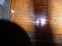
As requested, the motor plate and exciter plate information are included. The exciter was tagged #71764-3. 115 V. 2.4 A. Info from motor plate was: 3 HP, 690-2400 RPM, 12 Amps, 230 Volts, Shunt winding, Field Rheostat: 400 Ohms, 2400 RPM. Field volts; 115, Field max amps: 1.4. I retested the power to the coil and it was in fact 120 V DC. Attached are a couple of pics of the exciter/AC motor drive, the spindle DC motor plate and the relay diagram I found inside the cabinet. Unfortunately it does not have the coil specs. The forward and reverse contactor in the box is the diagram labeled 598. I want to thank everyone again for their help and insight. Bill, I may be contacting you about rewinding the coil.
John


John
Attachments
Similar threads
- Replies
- 10
- Views
- 367
- Replies
- 13
- Views
- 776
- Replies
- 14
- Views
- 601
- Replies
- 17
- Views
- 2K