Timothy Jones
Plastic
- Joined
- May 11, 2007
- Location
- Central Massachusetts
Some have pointed out that DC and AC motor controller switching transients and inductive voltage spikes can damage the insulation in electric motors (and other wound devices like transformers). Historically, some inverters and motor controllers (both AC and DC) are less than kind in their delivery of switching transients. For example, so called 'modified sine wave' AC motor controllers typically use MOSFET, IGBT, or bipolar transistor on-off switches to deliver voltage wave forms that are only step wise approximations to a smooth sine wave. The output of these controllers look a lot more like square waves than sin waves. "Inverter rated" motors have extra good insulation on the windings and are designed to resist the negative effect of these less than perfect controller electronics.
So the worry about SCR switching speeds in a solid state thyratron replacement is logical and justified.
I've done some tests to see what the differences in switching speed are between SCR solid state switches and the original C16J tubes in a modular 10ee lathe drive. My test drive has a 5hp Louis Allis DC motor. Ideally I would have liked to measure the voltage between armature windings directly, but as the motor armature is obviously rotating I don't see a way to do that. Instead, I took measurements across the rotating motor armature, the motor field windings, the modular drive main transformer (T5) secondary windings, and directly across the thyratrons.
A suggestion was made to do measurements with the motor loaded at half power in order to produce the most negative transient conditions. Since, on my test stand, I have only my hands on the motor pulley as a brake and have neither the skin nor the strength to make that very effective, I did tests under no-load conditions. Loading lengthens the thyratron on time, but doesn't seem to have much effect on the character of the switching transitions.
I did the tests at a base speed (mid position on the speed pot) with the armature voltage at maximum and the field unweakened.
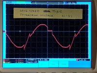
The first photo below shows about one cycle of the voltage across the armature (red) and the armature current (yellow) with the original C16J tubes. The ramp portion of the top trace is the period that the tube is conducting. At the start of conduction there is a sharp voltage transition, and then another at the end of conduction.
The second photo shows a close up of the start transition. The rise time is about 10 us, and there is a slight undershoot. The third photo shows a close up of the end transition. This is much slower and the rise time is more like 80 us.


