What's new
What's new

CVA Toolroom Lathe - Feed Gearbox

CarbideTip

Aluminum
Joined
Sep 21, 2016
Location
Woking, Surrey, UK.
Hi all,
In late 2016 I acquired a CVA toolroom lathe and as my existing rotary converter wasn't up to powering the 4HP motor I decided to rewire it completely with a new motor and VFD. That was finished a while back and I've used the lathe a bit since to get an idea of what else needs doing. It was made in 1961 so I wasn't too surprised that it wasn't oil tight in some places.
One of those places was the power feed shaft exit from the feed gearbox. I'm now in the process of fixing this.

For starters I read one of the posts here on removing the feed gearbox from a round-dial 10EE. That was most helpful, as the process is almost identical.

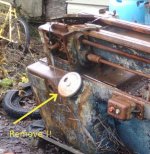
Added 2022: I forgot to mention that on CVA's the main gearbox speed selector wheel needs to be removed first. You cannot get the gearbox out with it in place.

SpeedSelector.jpg

P1010036.jpg

P1010043.jpg

The end cover was then easy to remove.
P1010046.jpg
At this point I was dismayed to see the mess.
It looks to me like the box has suffered from ingress of coolant, possibly running along the leadscrew and in via the broken seal.
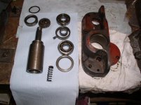
P6020011.jpg
The seals all seem to have been leather with a gaiter spring. Were 10EE's fitted with leather seals too?

I have ordered new bearings for the feed shaft and nitrile seals to replace the originals, but the worst part is that the bearings in the main gearbox.

Gbox_Bearings.jpg

The two bearings indicated are so bad that you can lift the shaft by about 1/16". If you lift the lower one it pushes the upper one up too!

I've now taken the front cover off too.

There was about 1/2" of brown sludge in the bottom of the gearbox, but as far as I can see there are no broken or missing teeth.
The uppermost bearings on the lead-screw shaft (which I've read are difficult to get A/C's in 10EE's) seem to be OK.
Incidentally, all the feeds were working prior to dismantling.

I've read (&re-read) dgfoster's account of replacing one of the gears on the cone shaft in a round dial 10EE, but I don't see how the shafts come out.

Help!

Martin.
 
Last edited:
Thanks Thermite, I'll study those threads.

This is dgfosters thread that I mentioned:

https://www.practicalmachinist.com/vb/monarch-lathes/step-step-round-dial-gearbox-removal-help-219110/?highlight=gearbox+disassembly

He (Denis) has obviously got the two shafts out but doesn't say how.
I was hoping that another CVA owner may have done this job in case there are differences between the 10EE and CVA.

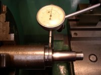
Another surprise was the amount of wear on the feed-shaft where the seal used to run.

P6100002.jpg

P6100003.jpg

So about 24 thou on diameter. The original diameter was 1.375" so (having first established I could get an under-size seal) I've machined it down to 1.3125". I'm not sure what grade of steel this was made of but it was very soft which might explain the amount of wear.
I was tempted to remake the shaft to keep the original seal size but the gear on the end has a woodruff key and a 'half & half' screw which would be difficult to match.

Thanks again Thermite.
Martin.
 
Another source of info is Collector on PM. He was working on one that I think is now at another wet coast shop. Worth a message to Collector if you’re stuck.

L7
 
Thanks Bill & L7.
I've sent a PM to Denis for help.

I have not had much time over the last few days, but the new bearings and seals for the output cover have arrived.
For the record:
Feed shaft output bearings: p/n LJ3/4 (1.875" OD x 0.750" ID x 0.5625 W) 2 required.
Feed shaft output oil seal Original p/n W20013731, SKF replacement CR13568 (2.000" OD x 1.375"ID x 0.313" W)
(I used a smaller ID seal (1.3125) as the shaft was worn & machined down to next available seal size)

Leadscrew shaft oil seal. Original p/n W18311243, SKF replacement CR11170 (1.828" OD x 1.125" ID x 0.250" W. NB Narrower than original)

Martin
 
I've made a little progress.
First the bearing caps have been removed from the cone shaft and clutch shaft. These are iron castings and have a tapped hole in the centre for removal. It's threaded 1/4" BSF, and I suppose I might mention at this point that all the screw fasteners on CVA's (at least of 1960's vintage) are either BSF (British Standard Fine) or BA (British Association). The BA ones include quite a lot of 3BA (eg The oil windows and slideway wiper covers) which might be difficult to get now.

P6200010.jpg

Next to come out was the clutch shifter rack. I only removed one of the plugged ends, but had to drill a hole in it to pull it out.


P6240019.jpg

There are three socket grub screws to remove. One is for the detent, the next stops the rack from rotating and the third is in the clutch shifter fork. With these removed the rack can be rotated and the shifter fork slid to one side so that it's woodruff key can be removed. The rack can then be removed.

P6240023.jpg

With this out of the way the access to the clutch and cone shafts is better but I'm still unsure how to proceed.
As I see it both shafts are captive and retained by the press-fit ball-races.
I've PM'd Collector and dgfoster to see if they can suggest how to proceed.

Martin
 
Clutch shaft removal...
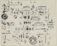
As far as I’m aware there is no good parts list for the CVA. If there is, and you have one I’d be grateful for a copy. Meantime I’ll use the one for the 1942 10EE which seems to be very similar.

Mon10EE_FdGbxP-diagram.jpg

The clutch gears (63 and 65) are free to rotate yet laterally captive on the shaft. They are constrained in one direction by shoulders on the shaft and by spacers (69 and 73) to the bearing inner rings in the other. What I was slow in seeing was that the gear 65 is smaller in diameter than the bearing hole in the main casting. So although the shaft cannot be removed to the left it can be to the right.

On the CVA the right bearings of both clutch (76) and cone (54) shafts are retained by rings pressed in after the bearings. There is no easy way to get these out so I drilled and tapped them for removal.

P6260036.jpg

The 10EE manual does not show these rings, but there seem to be circlips (68 & 74) which have no equivalent on the CVA. The CVA does have a circlip on the end of the clutch shaft to retain gear 66.

Since there is nothing to define the lateral position of the whole assembly I took depth mike readings from the machined surface on the right of the main casting to the bearing outer ring so that on re-assembly I should be able to get it back in the same place.

Using a soft copper drift and hammer I knocked the shaft out. Ideally the left bearing should stay put as there is not sufficient room in the gearbox for the combined width of gear 63 and the bearing. Mine started to move, but then stopped when 63 hit one of the gears on the cone shaft. A bit of light alloy between the two helps to prevent damage to the gears.
On the right the bearing must come out on the shaft. As soon as the shaft is free, spacer 69 and gear 63 come off. In my case the clutch gear 64 was tight on the part of the shaft where it doesn’t normally run, but came off with a bit of persuasion.

P6260024.jpg
P6260035.jpg

The clutch shaft bearings are 47mm OD x 20mm ID x 14mm wide. This is a common 6204 and I believe the same as the 10EE. So another place where the CVA is Copied Very Accurately from the 10EE.

The gears 63 and 65 have bronze bushes which have seen better days. Any suggestions for the grade of bronze to remake these? There’s an oval oil distribution groove on the inside which will be difficult to reproduce.

P6260030.jpg

I'm guessing that the approach to removing the cone shaft will be similar. It looks like this will have to go the other way.
 
Clutch & Cone shaft bearings

I've now got the cone shaft out too. I'll post some details for the next guy later, but I'd like to get the new bearings on order.
The originals are Hoffmann:

P7010048.jpg

As mentioned in the last post these are 47 x 20 x 14 (mm) which is a common 6204.
But should it be the C3 version as here:

https://www.practicalmachinist.com/vb/monarch-lathes/step-step-round-dial-gearbox-removal-help-219110/?highlight=gearbox+disassembly

I'm not a bearing expert, but my bearing supplier says that they're intended for hot/high speed applications.

Can someone tell me if I should go for the C3 version in this application?

Thanks.
 
Cone Shaft Removal

For starters if you’re about to do this on either a 10EE or CVA I’d recommend that you mark one side of all the gears on the cone shaft. As Denis (dgfoster) mentions in his thread the gears have bosses but are asymmetric. i.e. the gear teeth are not in the middle. The difference in the boss widths left to right is quite small.

P6300039.jpg

The three smallest gears on the left end of the shaft will go into the hole in the casting, so the shaft can be removed by pressing the right end to the left. As the bearings on mine are scrap I had no concerns about driving the shaft out with a hammer and soft drift. It might be better if the right bearing stays in the casting, but mine went through and into the gearbox on the shaft.

P6300041.jpg

A puller is then required to remove the left bearing from the shaft. (If the right bearing stays put in the casting, you could continue pushing the shaft through the all the gears).

P6300044.jpg

The spacer ring and three smallest gears can then be removed through the bearing hole. Mine were quite tight and this was awkward. With the three smallest gears off the shaft but all the other gears and RH bearing still in place it will just come out through the front of the gearbox. On a 10EE with its smaller round opening I doubt that this would be possible.

P6300046.jpg

The right bearing can then be removed with a puller.

I removed all the gears from the cone shaft for cleaning but they were very tight on the the key.
 
Tumbler Gear Removal

With the clutch and cone shafts removed, the tumbler gear can also be removed.
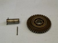
This is simply a case of removing one of the split pins and pushing out the shaft. Like the cone shaft gears the tumbler gear has asymmetric bosses, so be sure to note which way round it goes.

P7020049.jpg
P7020050.jpg

The bearing is 32 OD x 12 ID x 10 W (all mm) which is a 6201 and again the same as a 10EE.

I think that this will be as far as I go with the feed gearbox. The bearing in the tumbler gear will be replaced but isn’t too bad, and I’m coming to the conclusion that all the damage due to coolant ingress has been confined to the lower right of the gearbox. Perhaps if I were 20 years younger I’d rebuild the whole box, but as it is I still have to re-assemble this and there’s work to do in the apron too.

Further posts on re-assembly to follow.

BTW, Thanks are due to Denis (dgfoster) for his thread (and PM).
I also PM'd Collector but have had no response. Hope he's OK.
 
Those bearings look to be common non precision stamped steel cage bearings. I would not go C3 clearance unless they run towards the top end of their rpm limit ( 15000-18000 ). An SKF Explorer is an ABEC 3 that is pretty cheap but Cn ( standard ) clearance. If it is labeled JEM it is C3 and meant for hi hot or fast applications. Natchi Quest is similar and I suspect most companies now stock a slightly higher precision bearing to compete. Dave
 
Those bearings look to be common non precision stamped steel cage bearings. I would not go C3 clearance unless they run towards the top end of their rpm limit ( 15000-18000 ). An SKF Explorer is an ABEC 3 that is pretty cheap but Cn ( standard ) clearance. If it is labeled JEM it is C3 and meant for hi hot or fast applications. Natchi Quest is similar and I suspect most companies now stock a slightly higher precision bearing to compete. Dave

Thanks for the info. beckerkumm. I've never worked out what the maximum speed could be in these bearings but I doubt that it's anything like that. Top spindle speed on mine is around 3000 rpm (Highest rate from my main gearbox is 2220, then 50% over-speed from the VFD - 3110rpm). This is then reduced by a belt drive before it gets into the feed gearbox.

My bearing supplier is trying to decode the markings on the Hoffmann originals, but I'm coming to the conclusion that standard clearances will be fine.
Anyway, thanks again.
 
Seems like many of my old machines with replacement bearings have about a 50% chance of being incorrect. Hoover used a different numbering system. Their deep groove bearings used 7xxx rather than 6xxx and people replaced those with a single angular contact bearing instead. I think Hoffman used more standard nomenaclature. Other than spindle bearings on lathes, I've seen higher precision bearings on my woodworking machines than on my metal machines. I don't have nearly as many examples of mills as table saw and jointers though. Dave
 
A bit late here but I have a pristine parts manual for the CVA.

If you still need a scan or photocopy of any page I can send.

Should you need headstock bearings, I have a set of new *********, Germany, P4A, which I think are Abec 9 for runout etc and Abec 7 for dimensions.
 
Thanks Earl. Yes please for a scan of the feed gearbox page(s). I'll send a PM with my details.
I think (hope) the headstock is OK. I've done a few jobs on the machine without problems in this area.

The apron/saddle will be next on the list when the gearbox has been re-assembled.
 
Clutch Shaft Gear Bushes

Well 6 months have passed since the last update. So here’s the next part of the saga.

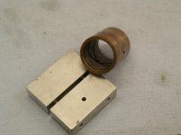
The clutch shaft gears 63 and 65 have bronze bushes which I decided to replace. The bushes are simple enough but have a figure of 8 pattern oil distribution groove cut on the inside.

P8160077.jpg

I mentioned the oil groove in an email to a friend, and about 10 minutes later got a reply with a link to this You-Tube video:

OIL GROOVE CUTTING - YouTube

In case the link gets broken here’s a still taken from it:
You-Tube.jpg

Alas no drawing but there was enough information in the video for me to make one. The gears need to have a 2:1 ratio to generate the correct pattern. Most of the material came from my ‘scrap’ box, but I had no bevel gears. These came from ebay and were relatively cheap.
They are 2 Mod. 20T and 40T.

Although the one in the video used a motorcycle chain in an unconventional manner, I found that a simple drive peg touching one of the chuck jaws worked just fine. If the bore in the bush had been much larger I think the chain would have been better since the boring bar, and centre of the bevel gear would be a long way from the lathe centre-line.

PB140002.jpg

And the first test cut in a scrap of brass:

PB140004.jpg

Here are the new bushes ready for pressing in:

PB170009.jpg
 
Clutch Shaft Gear Bushes

I've uploaded a short video of the lathe attachment used to create the oil grooves.


The two new bushes have been pressed back into the gears.

PB170010.jpg

It didn't quite go to plan! I had not made sufficient allowance for the contraction of the inside diameter when pressed in.
As a result the bushes were too tight and had to be lapped to get a nice running fit on the clutch shaft.
I used 'Timesaver' lapping compound and an expanding alloy mandrel.
 
CVA Feed Gearbox Removal - Update

When I removed my feed gearbox I had already removed the spindle speed selector wheel.
More recently I salvaged another feed gearbox from a scrap machine, and found that you cannot get the box out without taking the spindle speed selector wheel off.

GearBoxRemoval.jpg

The easiest way to do this is to undo the centre fixing (pin spanner needed). In the recess below there's a grub screw half in the wheel and half in the shaft. Remove this and the wheel should lift off. Be careful not to lose the key.

Martin
 
I've uploaded a short video of the lathe attachment used to create the oil grooves.

If you ever draw that up I'd like to see the plans, even something very rough. Looks handy.

The two new bushes have been pressed back into the gears.

It didn't quite go to plan! I had not made sufficient allowance for the contraction of the inside diameter when pressed in.
As a result the bushes were too tight and had to be lapped to get a nice running fit on the clutch shaft.
I used 'Timesaver' lapping compound and an expanding alloy mandrel.

That's pretty normal. I think you can find the expected bore reduction in tables (here? https://www.qbcbearings.com/TechInfo/PDF/SinteredMBearings.pdf ) but starting with the press difference is a good start with straight bronze. Lapping it out to nominal with Timesaver's is a good solution - I've used that on model engines and it works very well.
 
Drawings: I'm hoping to use this to improve my Fusion 360 skills, so I should be able to let you have some at some point....but it won't be for a while.
Thanks for the link on bearings. I'd not seen that before, but it seems to apply to sintered bearings. I guess that solid material would would be similar.

Martin.
 
Cone Shaft Gears

Whilst the cone and clutch shafts were out I examined them for any defects.

P1210038.jpg

In the process of doing this I tabulated the dimensions of the cone shaft gears. Not sure if this is of interest or use to anyone...

My Gearbox - Later Machines.

NotesTeethFace WidthBoss LeftBoss RightBoss WidthPart No.TPI A
Also meshes with clutch shaft240.3250.0000.0500.37513153.000
260.2700.0500.0550.37513163.250
Out of true270.2570.0620.0560.37513173.375
280.2700.0570.0510.37513183.500
300.2600.0520.0620.37413193.750
320.2600.0540.0640.37413204.000
Also meshes with clutch shaft360.3560.0090.0090.37413214.500
spacer0.7500.750no mark
380.2590.0610.0550.37513264.750
400.3020.0600.0120.37413225.000
440.2520.0720.0500.37513235.500
Meshes only with clutch shaft480.3560.0100.0070.374no mark

All dimensions in inches. Gears are 16DP.
Part Numbers are CVA of course.
The rightmost column represents the pitch that would be obtained with the A-B-C knob set to A.

The 27T gear appeared OK, but I could not get consistent measurements for the boss widths. In short the gear is not true with its bore. Spinning it in the lathe the gear wobbled left/right and up/down. WTF!
There’s no sign of physical damage so I have to conclude it was a duff one or suffered distortion during heat treatment. (these gears are hard!)

By chance I had the good fortune to acquire another almost complete box from a scrap machine. It’s older (1953) whereas mine is 1961. The cone shaft has some different gears as this earlier CVA had identical thread pitches to the round dial10EE. (ie 11.5TPI but no 19TPI).

Earlier Machines

NotesTeethFace WidthBoss LeftBoss RightBoss WidthPart No.TPI A
Also meshes with clutch shaft240.3170.0000.0600.375no mark3.000
260.2510.0630.0600.375no mark3.250
270.2470.0620.0680.375no mark3.375
280.2700.0600.0480.37513183.500
300.2500.0620.0650.376no mark3.750
face width varies. 065 to 071320.2450.0680.0590.37513204.000
Also meshes with clutch shaft360.3570.0110.0090.376no mark4.500
Spacer0.75no mark
400.2850.0310.0620.375no mark5.000
440.2540.0620.0610.376no mark5.500
460.2490.0650.0640.375no mark5.750
Meshes only with clutch shaft480.3540.0110.0110.375no mark

I have no idea why there are such variations in the dimensions in these two tables.

ConeShaftGears.jpg

I have now replaced the bent 27T gear on my cone shaft with the one from the scrapper and we’re ready to see if I can remember how it all goes back together!

Martin


Back
Top