CarbideTip
Aluminum
- Joined
- Sep 21, 2016
- Location
- Woking, Surrey, UK.
Hi folks,
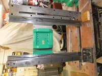
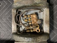
I’m gradually working through the things that need fixing on my 1961 CVA. The saddle and apron are both now off. Everything needs a good clean but the saddle lubrication pipes are worn through and will have to be replaced.

The pipes are 5/32” diameter copper which is easy enough to get.
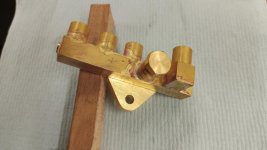
The 5 metering valves are all marked YL0 and carry the “Tecalemit” company logo.


On the CVA the 5 valves feed: Front saddle V way, Rear saddle flat way, left cross slide way, right cross slide way, cross slide feed screw thrust bearings (mine does not have the taper turning attachment so these are at the front rather than over the TTA).
The manifold and all the metering valves were full of muck. A friend advised me to contact Lubetec in Leeds (UK) for replacements. They were very helpful and although the valves I have were obsolete by 1963 they still had the catalogue page!

It’s interesting to note that even back then there was a connection with Bijur. Unfortunately they were unable to supply any direct replacements with 1/8” BSP threads on both ends. In the end I ordered new valves (AJB-0) with M8 x 1 metric threads and will either modify the existing manifold or make a new one. The new valves have the same flow rate as the old yet it seems odd to me that the cross-slide gets the same amount of oil as the saddle. There’s another valve in the apron that feeds the oil distribution there. This was marked YL2.
The manifold is made from a slab of steel with interconnecting holes to make the oil passages. All outlets are on the same side so one pipe loops underneath (well on top really) to feed the cross-slide on the tailstock side. I wonder why they didn’t put that outlet on the other side.

Any other CVA owners out there done this repair? I imagine fitting the new pipes will be ‘interesting’!
Martin
I’m gradually working through the things that need fixing on my 1961 CVA. The saddle and apron are both now off. Everything needs a good clean but the saddle lubrication pipes are worn through and will have to be replaced.

The pipes are 5/32” diameter copper which is easy enough to get.
The 5 metering valves are all marked YL0 and carry the “Tecalemit” company logo.


On the CVA the 5 valves feed: Front saddle V way, Rear saddle flat way, left cross slide way, right cross slide way, cross slide feed screw thrust bearings (mine does not have the taper turning attachment so these are at the front rather than over the TTA).
The manifold and all the metering valves were full of muck. A friend advised me to contact Lubetec in Leeds (UK) for replacements. They were very helpful and although the valves I have were obsolete by 1963 they still had the catalogue page!

It’s interesting to note that even back then there was a connection with Bijur. Unfortunately they were unable to supply any direct replacements with 1/8” BSP threads on both ends. In the end I ordered new valves (AJB-0) with M8 x 1 metric threads and will either modify the existing manifold or make a new one. The new valves have the same flow rate as the old yet it seems odd to me that the cross-slide gets the same amount of oil as the saddle. There’s another valve in the apron that feeds the oil distribution there. This was marked YL2.
The manifold is made from a slab of steel with interconnecting holes to make the oil passages. All outlets are on the same side so one pipe loops underneath (well on top really) to feed the cross-slide on the tailstock side. I wonder why they didn’t put that outlet on the other side.

Any other CVA owners out there done this repair? I imagine fitting the new pipes will be ‘interesting’!
Martin


