What's new
What's new

EE Front spindle bearing fit up

AlfaGTA

Diamond
Joined
Dec 13, 2002
Location
Benicia California USA
I have a 62' EE that i have had apart for some time (years)
Started a rebuild and got distracted.
I am back at it now and questions keep cropping up.

If i measure the depth of the counter bore that carries the flange on the front spindle bearing i get
.1955" to .196" depth in the front bolt on cover.

The original gasket (as removed) measures:
.0295"-.030" (assume original was nominal 1/32" stock

The flange thickness on the bearing measures:
.216"

Looks like this gives total height of counter bore + gasket of :
.2255"

Looks like there is .0095" of clearance between the flange and cover...

Does not seem correct. Anyone here been in this ? Do the numbers seem correct?

Most gasket stock comes in 1/64" steps so even if the gasket was incorrect the next thinner stock would be at 1/64" (.0156" nominal)
Which looks to give around .005" of interference which would mean that the gasket would not be in compression....
Is the factory gasket special (non standard) thickness, or ?????
Seems like one would wish to have the bearing captured for both right hand and left hand thrust.....
Thoughts ?

Cheers Ross
 
:confused:

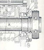
Flange of (front precision New Departure angular contact ball bearing on such as P&W C ) sits on face of head stock casting and has nothing to do with flange style cover/ gasket (other than being captured by)

Scan from parts book

PW Front brg.jpg
 
I've never had mine apart to that degree. One manual seems to show the gasket under the bearing flange, such that the design counts on the nose cover pinching the flange against the front of the headstock with a gasket in between. That seems wrong. The 1965 manual on the 'net calls out the gasket but shows no thickness for it. That drawing shows the flange blocking the bottom oil drain, which also seems strange. My guess is that the gasket you have is too thick and that you want the flange pinched metal-to-metal against the front of the headstock.
 
I hate to comment cause my memory of this event is so far in the past. But I do remember forgetting to install the gasket( due to the excitement at the time), and having to slit it in order to slide into place, and when nipping it all up, that the compression of the flange against it (gasket) was minimal.
 
1965 manual on the 'net calls out the gasket but shows no thickness for it. That drawing shows the flange blocking the bottom oil drain, which also seems strange. My guess is that the gasket you have is too thick and that you want the flange pinched metal-to-metal against the front of the headstock.

The gasket i have is made to clear the OD of the flange, so it is part of the total height or clearance package.
Mine has a hole in the gasket for the drain hole.

Could be the wrong thickness. Might be shop made, its hard to tell. Bolt holes don't look die cut, but the gasket is old and dried out from being out of the machine for some time.
Thanks fro the replies...
Cheers Ross
 
:confused:

Flange of (front precision New Departure angular contact ball bearing on such as P&W C ) sits on face of head stock casting and has nothing to do with flange style cover/ gasket (other than being captured by)

Scan from parts book

View attachment 321342


I must be missing something here. 10EE spindles should be supported by a PAIR of AC bearings something like the attached photo. Your scan is only showing a single row bearing so I'm not sure what that is and how relative it is to this discussion about stack up clearances and such. The gasket thickness should not play into anything related to bearing loading and such but may play into capturing one of the bearings to lock down axial movement.
HS Capture.JPG
 
Bob:
Don't think that is correct. Section drawings clearly show a gasket....Is your machine a EE , if so what year?
On my machine i could not get the cover to pull up tight against the face of the head stock casting w/o a gasket (shim)....leaves a gap that will leak oil.

Cheers Ross

On reflection and some thought, think the gasket needs to be thick enough to give some clearance to the flange on the front bearing. Don't think Monarch would
want the cover leaning on the bearing, could affect alignment or geometry.
Having clearance gives all the hard positive axial location from the flange on loads going toward the head stock (right hand turning)
Any left hand turning would be generally accompanied with a supporting tail stock so no bearing movement.
Further there is some interference in the housing which would help prevent bearing movement....

Later head stocks (single sight glass) added a retaining screw to the outer ring of the rear spindle bearing slinger which would have added a 2and level of restraint.
 
I am fairly certain that the bearing flange is meant to be pinched between the headstock and front cover. That provides positive location in both thrust directions. The gasket thickness needs to be set so that it just squeezes enough when the bearing flange pinches. A cork gasket like back In the day would have enough squish without stopping the bearing flange from being pinched.

The headstock ledge that the flange sits against is machined perpendicular to the bearing bores. There's no reason that can't be precise as made my Monarch. I don't think you can count on the oil flinger setscrew at the rear of the bearing stack to take any thrust, beside the fact that it is only on one side (big offset from the load path).

See these old posts:
https://www.practicalmachinist.com/vb/monarch-lathes/ee-spindle-bearing-removal-99522/#post319634
https://www.practicalmachinist.com/vb/monarch-lathes/10ee-spindle-removal-219128/#post2481757
 
I have a 62' EE that i have had apart for some time (years)
Started a rebuild and got distracted.
I am back at it now and questions keep cropping up.

If i measure the depth of the counter bore that carries the flange on the front spindle bearing i get
.1955" to .196" depth in the front bolt on cover.

The original gasket (as removed) measures:
.0295"-.030" (assume original was nominal 1/32" stock

The flange thickness on the bearing measures:
.216"

Looks like this gives total height of counter bore + gasket of :
.2255"

Looks like there is .0095" of clearance between the flange and cover...

Does not seem correct. Anyone here been in this ? Do the numbers seem correct?

Most gasket stock comes in 1/64" steps so even if the gasket was incorrect the next thinner stock would be at 1/64" (.0156" nominal)
Which looks to give around .005" of interference which would mean that the gasket would not be in compression....
Is the factory gasket special (non standard) thickness, or ?????
Seems like one would wish to have the bearing captured for both right hand and left hand thrust.....
Thoughts ?

Cheers Ross

Ross,

The original gaskets are .012" thick (used gaskets, so they may have compressed). The gaskets Monarch currently supplies are .015"-.016" (1/64") thick. They are fiber gaskets, not cork. I think the gasket should be slightly compressed when fitted and the outer shell of the front bearing should be clamped in place by the cover so there is no possibility of movement.

The gaskets for the rear spindle cover are the same thickness.

I think you are right about the fit being important at both ends. Monarch changed the design of the rear bearing setup at some point in the late 60's to angular contact. Is that what you have? The angular contact setup is held in place with a nut on the end of the spindle that compresses the stack of parts (feed pulley, drive pulley, spindle lock, inner bearing races and spacer, and then the rear cover locates the outer bearing races. The earlier design is different: the rear cover locates the outer bearing race but the inner race of the 5210 floats on the spindle. With the earlier setup it is important to use an early New Departure 5210 bearing, which has a different design than the later 5210. There are some 5210's currently on Ebay with the part number 55510 (they have shields which need to be removed).

-Dave
 
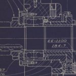
The blueprint view in the 1965 manual shows that the rear bearing stack can float axially in its headstock bore. That is what I would expect. If the rear bearing pair were unable to float, the design would be over constrained, and the axial preload would be uncontrolled and left to the whims of thermal expansion between the front and rear bearing stacks. If the rear stack is able to float in the headstock bore, the bearing preload is controlled separately within each stack by the spacer lengths at the inner and outer rings. That is the textbook way to design angular contact bearing arrangements.
Screen Shot 2021-05-20 at 9.33.47 AM.jpg
 
Rich, can you also post the portion of the drawing that shows the oil slinger/dam that is just behind the front bearings? I want to see the part number for the dam (the part that is pressed into the headstock), so I will know if that is the same part that is used in an earlier headstock. The oil slinger changed design, probably at the same time as angular contact bearings were introduced. I am fitting a new spindle into the 49 mfg. lathe, to add threading, and the spindle I have is from a late 60's machine. It is complete with the new oil slinger, so I need to know if the dam has to be replaced in the 49 headstock.
 
Rich, can you also post the portion of the drawing that shows the oil slinger/dam that is just behind the front bearings? I want to see the part number for the dam (the part that is pressed into the headstock), so I will know if that is the same part that is used in an earlier headstock. The oil slinger changed design, probably at the same time as angular contact bearings were introduced. I am fitting a new spindle into the 49 mfg. lathe, to add threading, and the spindle I have is from a late 60's machine. It is complete with the new oil slinger, so I need to know if the dam has to be replaced in the 49 headstock.
The drawing from post #6 appears to be a section of Monarch drawing 202.268, the version from 1969. This is for the single oil sight glass version of the headstock, which is circa 1967. This would be correct for OP's headstock, but not for yours.

The oil slinger design was changed from the early square-dial headstocks. I'll e-mail you the 1944 square-dial headstock drawing.

Cal

Thanks Cal. I am using the early oil slinger. The late oil slinger requires both a setscrew from the top and a pin on the bottom, neither of which are easily fitted to a 49 headstock.

I think there must be an intermediate headstock drawing between the early square dial and the single sight glass headstock. Some of the changes shown in the later drawing actually happened earlier. For example, my 59 10EE has the newer style spindle lock and tachometer, both of which required some changes to the casting and machining of the headstock.
 
Late to the party but.................When I reassembled my 1964 headstock I used brown paper, home made gaskets on the front seal plate. Don't remember how many but it was at least two.I still have a seep there but at least I know there is oil getting to the bearing.


Back
Top