What's new
What's new

Feed rod drive mismatch

jrlandau

Aluminum
Joined
Jan 28, 2003
Location
San Jose CA USA
I am restoring a 10EE (1956) that I have never used.

Reassembling the feed rod drive (after removing and cleaning up the apron and replacing it), I was surprised to find that the two parts that ought to match, don't. That is, when the two dogs engage their slots, the screw holes in the 2 parts of the cover are not aligned, nor are the pins with their holes. There is a witness mark that isn't lined up, either. And the RH half of the cover has 2 screw holes, the LH half four! Am I missing something? A brain? And if not, how to tackle it?

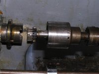
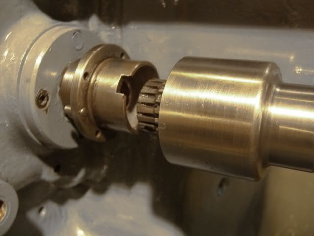
Here are the 2 parts of the drive (the spring is left out for the photo)
Feedroddriveapart-1.jpg


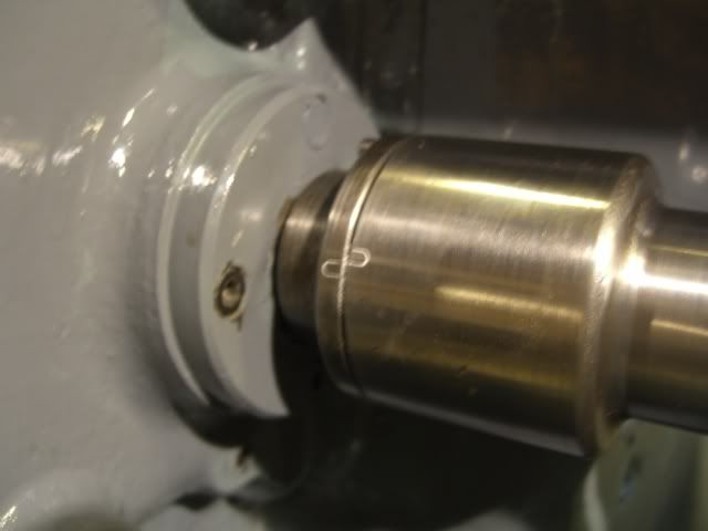
Here are the 2 parts with the dogs engaged--you can see the witness marks mismatched.

FeedRoddrive.jpg


Any help would be appreciated.

Joe
 
The witness mark looks odd. The original marks are not so elongated, I strongly suspect those parts were not a matched pair from the factory. It's possible you have parts from two different machines there.

First questions, are those the parts you disassembled and were they assembled with all four screws?

If yes to both, then try rotating the two parts 180 degrees and see if they will assemble. In other words ignore the witness marks (they don't match anyway) and try it the other way.

If these parts have not been assembled before, all is not lost but there will be more rework involved to properly mate them together. Take the first step above. If it doesn't work then you can address the situation.

On edit: Sorry, I was a hurry this morning. Thanks for posting the drawing Cal.

The alignment/shear pins (511-1) in the flange of of EE-3634 must engage their corresponding holes in the outer body (EE-3632). The ends of the pins should be about flush with the left hand side of the flange, you need to move them to the correct extension from the right hand side of the flange. The pins also determine clocking of the two parts. If you can mate them and the screw holes line up you're good to go. Make your own new witness mark if needed.

The witness mark was applied after the matched assembly of EE-3634 and EE-3632 was mated at the factory. That's why parts that weren't originally mated at Monarch won't necessarily have matching witness marks. They may or may not assemble either, sometimes luck is good.

Try assembling them in both clockings and see how it goes.

The internal spline portion of the dog clutch (EE-3635) should be a slip fit into the body (EE-3632). It is positively clocked to and driven by tabs which fit into notches in EE-3634.

The first photo shows mine being disassembled, the second shows the positions of the pins (yours should extend like these) and the drive notch positions in the end of EE-3634. It also shows the four tapped screw holes and the two holes which take the pins in EE-3632.
 

Attachments

  • Feed rod clutch disassembly.jpg
    Feed rod clutch disassembly.jpg
    61.8 KB · Views: 1,921
  • Feed rod clutch.jpg
    Feed rod clutch.jpg
    79 KB · Views: 594
Last edited:
That's pretty odd. I think Dave is correct about these parts being from different machines.

attachment.php


It looks like the plunger [EE-3631] and spring are missing. Note also that the dowel pin [511-1] is backed out.

Is it possible that the internal spline [EE-3635] managed to rotate inside the shell [EE-3632] while it was apart? Is the internal spline pressed into the shell, or is it maybe held with a set screw or pin?

Cal
 

Attachments

  • 201073_feed_clutch_detail.jpg
    201073_feed_clutch_detail.jpg
    40.4 KB · Views: 3,765
I am the one who disassembled these parts. They were held with a single, somewhat mangled screw, and I can't figure out how even one screw fit. Something may indeed have rotated since disassembly.

I have tried both orientations. When I get the alignment pins aligned, the tabs don't mate with the notches (and vice versa). I am glad to learn that the internal spline portion of the dog clutch may be a slip fit into the body--if I can rotate the body a bit relative to the internal spline (which I think must carry the tabs) then it will all align.

I will take it apart (at least try).

Cal, that's a great drawing--much better than the one in my manual.

Thanks to everyone.

Joe
 
Joe, the internal spline portion of the dog clutch is indeed a slip fit, it isn't the determinate clocking feature. The pins are. Long time goop and or corrosion can make those parts stick together. Free them up.

Your observation of one mangled screw holding the pieces together further suggests the parts didn't meet at Monarch as a matched set.
 
Take out the spring and bronze spud that pushes on the end of the shaft. Push back the alignment pins. Try the 4 possible positions of the mating pieces, look for one where the screws and pins mate - ignoring the match marks (that I don't think are Monarch anyway). If you don't find a position that works with the pins use one that works with the screws - often these parts were pinned by hand after assembly, and it's possible that someone mixed these sometime after Monarch shipped the lathe. When you have it working mark it and put the spud and spring back in on final assembly (don't forget to grease the dog teeth).

All in all it'd be better to run this with 4 screws rather than one pin.
 
Dave,

Are you saying that the internal spline [EE-3635] should be free to rotate inside the shell [EE-3632]?

Cal

Yes. For a square dial it is, can't speak for a round dial.

When the feed rod clutch is assembled the internal spine is keyed to the gearbox output shaft (EE-3634) by the two notches shown in my photos. The internal spline piece has two protruding driving features that mate with these notches. Thus, in the assembly it isn't free to rotate.

Also, note that the feed rod driving torque is transmitted only by these mating features, it is not carried by the joint between the output shaft (EE-3634) and the outer housing (EE-3632).

In light of that, as Russ suggests, it's better to have all four screws holding the assembly together than one buggered screw and two pins. This joint doesn't transmit torque but it is loaded axially.
 
Yes. For a square dial it is, can't speak for a round dial.
On the later round-dial the internal spline is broached into the hood so it can't rotate independently.

When the feed rod clutch is assembled the internal spine is keyed to the gearbox output shaft (EE-3634) by the two notches shown in my photos. The internal spline piece has two protruding driving features that mate with these notches. Thus, in the assembly it isn't free to rotate.

Also, note that the feed rod driving torque is transmitted only by these mating features, it is not carried by the joint between the output shaft (EE-3634) and the outer housing (EE-3632).
...
OK, that's what I thought, except the part about "the assembly it isn't free to rotate" confuses me a bit. I assume you mean the outer housing (hood) isn't free to rotate once it's been screwed to the output shaft?

Let me try rephrasing it, just to see if I understand:

The feed-rod stub shaft from the gearbox [EE-3634] has two notches machined in it. These notches drive the internal spline [EE-3635] via mating tabs. The internal spline meshes with the external spline [EE-3636], which is pinned to the end of the feed-rod via a taper pin [438-4].

The shell [EE-3632] aligns the internal spline [EE-3635] to the external spline [EE-3636] and feed-rod when the clutch disengages and also protects the splines from dirt. The shell is a clearance fit to the internal spline and does not drive it or the feed rod. With the 4 screws [123-7] and the dowel pin [511-1] removed, the shell should be free to rotate relative to the internal spline [EE-3635] and the feed rod.

So, if I have it right, Joe should be able to rotate the shell until the screws holes line up, which may or may not allow the dowel pin holes to line up. Sound right?

attachment.php


Joe, do you have the plunger [EE-3631] and spring [EE-2432]?

Cal
 
OK, great. So Joe's problem turns out to have a simple fix. He just needs to free up the internal spline so that it will turn inside the outer housing/hood and he should be able to line things up. If the dowel pin will go in and the witness marks line up, then the two halves are original.

Cal
 
Got it. I do have the spring and plunger. I had tried to rotate the outer housing while the tabs were engaged in the notches, but it wouldn't move, at least not easily. Sounds like the outer housing and the spline are stuck together with 50 years' worth of stuff. It's time to disassemble. Thanks.

Joe
 
For future readers. The half of the dog clutch in the right/shell half can,and will, rotate causing the two shell halfs to refuse to align during reassembly. The dog clutch in the left half is a friction fit and can be tapped back into alignment. My 1954 MG (former Defense Department machine) had an inspection stamp, but no alignment marks.

Ron
 
This is a lot of words for a simple assembly. When the spring pushes right, the feedscrew splines mate with the internal splines and the outer shell drives the feedscrew. When the apron pushes on the big setscrew collar and moves the feedscrew left, disengaging the splines, the outer shell keeps rotating but doesn't rotate the feedscrew, and the apron stops moving. Thus it is an automatic feed disengage. My outer shell halves had an "O" stamped next to one of the holes on both the left and right halves to indicate the alignment. A real nuisance using an L wrench for the 4 8-32 socket head bolts holding the halves together.
 
This is a lot of words for a simple assembly. When the spring pushes right, the feedscrew splines mate with the internal splines and the outer shell drives the feedscrew. When the apron pushes on the big setscrew collar and moves the feedscrew left, disengaging the splines, the outer shell keeps rotating but doesn't rotate the feedscrew, and the apron stops moving. Thus it is an automatic feed disengage. My outer shell halves had an "O" stamped next to one of the holes on both the left and right halves to indicate the alignment. A real nuisance using an L wrench for the 4 8-32 socket head bolts holding the halves together.

Try it with slotted head screws. I replaced them with SHCS for ease of disassembly.


Back
Top