What's new
What's new

Filtering for smoother running on thyratron controlled 10EE

9100

Diamond
Joined
Nov 1, 2004
Location
Webster Groves, MO
I maintain a Modular 10EE that recently needed a general tune up. In the process I was running it in direct drive with the drive belts off. At a very low speed, I could feel a strong 120 cycle vibration on the pulley, not surprising because the drive at that speed is a series of short pulses with large gaps between. My Reliance MG lathe doesn't have the problem because the generator is supplying something close to pure DC.

Considering a fliter for the thyratron lathes, a capacitor would work, but it would be working very hard. A reactor is another possibility, but it looks to me that after the pulse the reactor would put a negative spike into the thyratron cathodes, possibly keeping them firing. It might pull the cathodes far enough negative to make them sufficiently negative to the grids that the one on the next half cycle would fire, sending the system into full output.

It seems like a diode with the cathode connected to the thyratron transformer's center taps and its anode to the common would prevent this. It would also give the reactor a level to work against. The reactor would be connected in series with the contacts of the forward and reverse contactors.

That seems like it should work. Comments?

Bill
 
That seems like it should work. Comments?

The armature should be acting as a pretty honkin' big reactor already, but with the belts off you're not getting the added benefit of the spindle and chuck mass. Maybe with those it'd be different?

If it doesn't change with the additional mass I think the cap idea might work, but it would take some pretty big caps and it'd be frequency sensitive. Maybe something to cut it in at abnormally low speeds?
 
The armature is a reactor all right but when the thyratron feeding it shuts off, the armature is disconnected from anything until the other thyratron fires. If you apply a positive voltage to an inductance to build up a field then disconnect it, you will get a large negative pulse back, so called inductive kickback. If you make a clean break, there will be no current in the winding and the magnetic field will not be maintained as it would be if the coil was shorted. Relays are often made to slow release by putting a diode with its polarity reversed to the applied DC or half wave rectified AC, which keeps a circulating current going until it exhausts itself through ohmic and core losses.

Having the spindle and chuck disconnected afforded a better feel of the vibration. Belt stretch and mass will dampen it, but it is still there, worse than it would be if it was fed low voltage rectified AC because the output of a thyratron or SCR is controlled by firing late in the cycle. The result is 120 pulses per second, that is every 8.3 milliseconds, but the pulse width may only be a millisecond or two vs a rectified AC waveform that is the positive half of a sine wave stretched over the entire 8.3 Ms.

I have a 15 hp DC motor on my Sheldon lathe with full wave rectified AC applied to the field with no filtering needed because of the field's inductance that is always connected to a definite voltage, not cut loose as it is with thyratrons. Likewise the armature fed with a full wave three phase bridge controlled by a three section Variac, which gives low ripple DC.

In fact, just a reversed diode might help. The problem is that the lathe belongs to someone else. We are on very good terms, but we might not continue to be if I blew up their thyratrons, so I am limited in the experimentation I can do. I guess I could rig an SCR supply for my MG 10EE, but that would be a lot of work just to prove a point.

Bill
 
Good conversation, interested in where it goes and hope I learn some. Here I'm just trying to keep up with the conversation as I just know enough about the electrical arts(science) to be dangerous. I do know that inductors are finicky things and and can "kick" voltages up to keep themselves happy. What do they say, they resist against changes in current? Voltages bump up and down accordingly? Maybe this is just inductors 101 that everyone knows already....sorry to ramble and not help the problem
 
Interesting idea.

I tried putting a 100uf motor run capacitor between circuit 49 and 51 to see what would happen. It did smooth out the voltage across the armature quite a bit (as measured on my scope). At low rpm, however, I couldn't detect any or much difference in the 120 hz vibration. There were however at least two negative side effects. First, my quick slow down relay works off the armature ripple voltage. This ripple voltage has to be present to turn off the brake, so when you filter it, you peg the brake on! To test I had to disable the QSD relay. The second negative effect I noticed was a distinct disruption of the speed regulation feedback which operates thru the compensation circuit. In other words, the control had trouble maintaining the rock solid speed regulation that I am accustomed to.
 
There is some differences in the operation under load of the MG and Module drives.
For example,Module drive, when setting the speed compensation under an applied load at 200rpms, open belt, a vibration can certainly be felt when the compensation circuit kicks in, but disappears as the speed is increased to 300rpms
At very slow speeds in open belt is where the problem is, but why run the machine like that when the practical solution is to use back gear and have full power.

I suppose a related problem would be a worn backgear unit, where running it fast causes vibration of its own. Then, one would try to run open belt as much as possible at lower speeds.
 
The QSD relay is simply reading the current drawn by the motor so it should be possible to adjust it for any reasonable current. Likewise, there should be a compensation setting that will work properly. It is an interesting example of unintended consequences.

Donie, I did consider working in back gear. This is more of a theoretical exercise than a practical one since I do not own a Modular lathe. I did run into similar issues experimenting with saturable reactors instead of my MG supply, which produce a pulse much like a thyratron or SCR but with a rounded peak lacking the higher harmonics. It took a lot of capacity and they are worked very hard, which made me consider a reactor filter instead. The real answer in that case was a three phase saturable reactor, which worked very well, but of course requires good quality three phase, none of the goopy outputs from most converters.

Bill
 
There also seems to be a big difference in the early 3hp dc motors that are larger then some 50hp 3phase motors, and the later 5hp dc motor that is about the size of a 5hp 3phase motor. The heavy armature in the old 3hp probably has some effect.
There is more of dead zone at low speed with the module drive, and its much smaller but more powerful motor. I run into that when cutting threads or leads at higher speeds, leaving the halfnuts locked in, and depending on the dynamic brake to stop. There is a point depending on what I am trying to do, that its either in back gear, or running the drive motor slow in open belt.
I that is less of an issue with the MG drive.

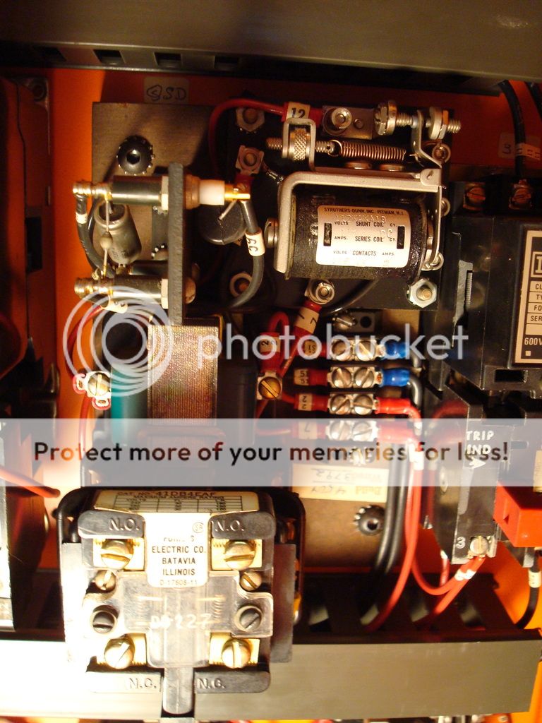
The Quick Slow Down relay on older modular drives, the very large round coil visible in the right hand compartment, was replaced by this unit. This solved many speed related problems,
As can be seen, it uses one of the regular relays along with other switch components and a heavy duty bridge rectifier, upper left.
 
I have a 15 hp DC motor on my Sheldon lathe with full wave rectified AC applied to the field with no filtering needed because of the field's inductance that is always connected to a definite voltage, not cut loose as it is with thyratrons.

The term 'cut loose' is interesting. It's not consistent with my understanding of thyratron operation where current continues to flow after the thyratron has been triggered until the forward current drops to zero. So even though the AC mains voltage has hit zero, an inductive load will be able to 'freewheel'. Once the forward current through the thyratron drops to zero, it deionizes, shuts off, and doesn't conduct until triggered again.

This might be of interest:

Dropbox - Thyratron Manual.pdf
 
Here are two simplified diagrams. At the moment the circuit has a positive voltage on the top lead and negative on the lower one. When the switch is closed, a positive current flows through the inductor and the motor. When the switch is opened, the inductor's field collapse produces a pulse that is positive on the right end and negative on the left. Because the circuit is incomplete, the pulse lasts until the field collapses as far as it is going to, close to zero because the inductor will have an air gap in the core, and the motor is unaffected. Of course, this is ignoring any arcs in the switch contacts and possible secondary triggering of a thyratron if one is substituted for the switch. In a circuit like the Monarch's, when the thyratron in question shuts off as the AC voltage nears zero there will be a back voltage from the inductor which works against that voltage, extending the pulse to the motor a bit, but once the thyratron shuts off, there will be no more current supplied to the motor. The other thyratron is out of the action because it will not be triggered until near the end of the other half cycle.

It seems that adding a diode as shown in the second diagram will cure the problem. A capacitor would help but it is going to be carrying heavy currents and it will need to be built for that service. OTOH., I can make any size inductor suitable with heavy enough wire to handle the current.

Ignore the fuzz on the diagrams. I have to go through a convoluted process to get an Autocad drawing into a JPEG and it didn't seem worth all the extra fiddling when the meaning should be clear enough.

Bill

Forgot to attach the diagrams.
 

Attachments

  • Monarch 2.jpg
    Monarch 2.jpg
    73.7 KB · Views: 90
Last edited:
Here are two simplified diagrams. At the moment the circuit has a positive voltage on the top lead and negative on the lower one. When the switch is closed, a positive current flows through the inductor and the motor. When the switch is opened, the inductor's field collapse produces a pulse that is positive on the right end and negative on the left. Because the circuit is incomplete, the pulse lasts until the field collapses as far as it is going to, close to zero because the inductor will have an air gap in the core, and the motor is unaffected. Of course, this is ignoring any arcs in the switch contacts and possible secondary triggering of a thyratron if one is substituted for the switch. In a circuit like the Monarch's, when the thyratron in question shuts off as the AC voltage nears zero there will be a back voltage from the inductor which works against that voltage, extending the pulse to the motor a bit, but once the thyratron shuts off, there will be no more current supplied to the motor. The other thyratron is out of the action because it will not be triggered until near the end of the other half cycle.

It seems that adding a diode as shown in the second diagram will cure the problem. A capacitor would help but it is going to be carrying heavy currents and it will need to be built for that service. OTOH., I can make any size inductor suitable with heavy enough wire to handle the current.

Ignore the fuzz on the diagrams. I have to go through a convoluted process to get an Autocad drawing into a JPEG and it didn't seem worth all the extra fiddling when the meaning should be clear enough.

Bill
A screen capture should be easy to do.
 
Thanks for interesting posts, as an old electronics guy that started out in tubes, but strictly a newbie to machine tools, I had no idea thyratrons were used for speed control in lathes. Now I have a whole new area to try to understand. Is this pretty much a Monarch thing, or common to others as well?
 
Thanks for interesting posts, as an old electronics guy that started out in tubes, but strictly a newbie to machine tools, I had no idea thyratrons were used for speed control in lathes. Now I have a whole new area to try to understand. Is this pretty much a Monarch thing, or common to others as well?

I don't know how many lathes used thyratrons but they were used in a lot of speed controls. 40 years ago I maintained a letter sorting machine at Monsanto world headquarters that had hundreds of feet of roller chain with cleats that dragged the letters past bins that opened when the right letter came up. A vacuum arm picked up each letter and held it up long enough for a typist to enter the first five letters of the addressee's name. Then it was dumped on the chain and a computer kept track of its position. It had a 5 hp motor to drag all that chain around. The motor was controlled by thyratrons in the same manner as the lathe except that it ran on three phase power with the thyratrons in a full wave bridge. Three thyratrons were phase controlled and to complete the bridge, it had three more that fired over the entire half wave, just acting as expensive diodes.

My first assignment when I got into the R&D business was to make a temperature control for a gyro using a 2D21 thyratron controlling a relay. The firing point on the damned thing changed with temperature, ambient light, phases of the moon and my maiden aunt's menstrual cycle. That was the last time I designed anything with a thyratron and mercifully SCRs came along, sending them into deserved obsolescence.

Bill
 
A screen capture should be easy to do.

Yes, there should be a better way. I have been exporting Autocad as a WMF file, about my only option, and converting them to JPEGs with Corel 9. Corel doesn't like WMFs one bit and does all sorts of funny things to them.

Bill
 
... In a circuit like the Monarch's, when the thyratron in question shuts off as the AC voltage nears zero ...

That's the premise I disagree with.

It's my understanding that a thyratron does not necessarily shut off as the AC voltage nears zero. It shuts off when the forward current nears zero. Therefore, it doesn't need the freewheeling diode.

In other words, a thyratron is not the 'ideal' switch you depict in your diagram. If it was, I'd agree on the need for the diode if the load was inductive.
 
Thanks for interesting posts, as an old electronics guy that started out in tubes, but strictly a newbie to machine tools, I had no idea thyratrons were used for speed control in lathes. Now I have a whole new area to try to understand. Is this pretty much a Monarch thing, or common to others as well?

Hendey, at one time used thyratron tubes, on their toolmakers lathe, it was not successful it used smaller tubes, they went to an even worse drive after.

This is an interesting thread, but it is sort of a minor problem if a problem at all in actual operation of the machine, operation and maintaining the machine is my strong point. Myself, I would hesitate to make any non factory modifications, and I am not electronically skilled enough to do so.


The advantage of both the motor generator, and tube dc drives is the variable speed and dynamic braking.
The later tube drive adds faster slow down and acceleration when using the speed control knob, and speed under load compensation-within the ability of the 5hp drive motor. This feature becomes valuable when machining alloys that are work hardening, or hard, and maintaining speed when using exotic tooling prone to break on speed decrease under load. The drives dynamic braking and acceleration circuits will bring the machine to top speed in about two seconds, and will bring the machine to a full stop from any speed in about two seconds. The speed control. start stop precision, makes threading operations much improved due to higher speeds can be used, taking better advantage of carbide, threading to the bottom of blind holes for example.
There is no other manual lathe that even comes close to that performance. An experienced driver can take real advantage of that
Pretty much, the evolution of the drive systems, and machine itself goes along with needs of the defense/nuclear industry and the materials used.

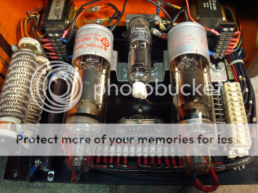
Looking down on the tube board on a module drive machine 1960 to 1983.
The coils at left are the braking resisters. The two big tubes are armature, the small one, motor field.
 
The advantage of both the motor generator, and tube dc drives is the variable speed and dynamic braking.
The later tube drive adds faster slow down and acceleration when using the speed control knob, and speed under load compensation-within the ability of the 5hp drive motor.

Thanks much for the great description and photo, I was really wanting to see how it looked. The motor-generator is an earlier design, also using a DC motor? I think the only thing I did with thyratrons was use one in an oscilloscope I built for a science project in the 9th grade. This would have been 1957, but I used the schematic of a scope I found in my older brother's 1945 ARRL ham radio book. The circuit is a relaxation oscillator, outputs a sawtooth waveform which can be synchronized with another signal.
ThyratronSweepCircuit.jpg
 
Thanks much for the great description and photo, I was really wanting to see how it looked. The motor-generator is an earlier design, also using a DC motor? I think the only thing I did with thyratrons was use one in an oscilloscope I built for a science project in the 9th grade. This would have been 1957, but I used the schematic of a scope I found in my older brother's 1945 ARRL ham radio book. The circuit is a relaxation oscillator, outputs a sawtooth waveform which can be synchronized with another signal.
View attachment 252078
I being an old tube man I also used a thyraton for making a pulse for a magnetron 100KW
 
The Motor Generator machines 40s to about mid 1950s, long ago called motor driven by used machine dealers back some years, uses a 3phase ac motor to drive a dc 220volt generator, with a driven 120volt dc field exciter, this through the controls drives the 3hp dc spindle drive motor.

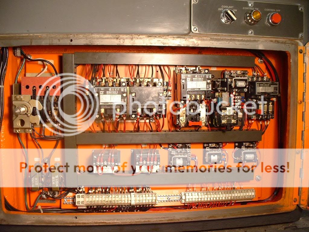
The photo above is called the electronic compartment, that is the lefthand door under the headstock, Module drive. The photo below is the righthand electrical compartment containing the multiple switches and relays to make all of those spindle control functions work.
There are 88 wires in the machine pictured, no less then 8 transformers. many relays and switches. So, one of the prices that has to be paid is good maintenance. That said, once one becomes familiar with the functions of the drive, any problems can usually fixed quickly, often related to the small field tube or replaceable diodes in the control module.
Actually each circuit is simple, its more of a challenge to find that problem circuit right off.
 
Thanks much for the great description and photo, I was really wanting to see how it looked. The motor-generator is an earlier design, also using a DC motor? I think the only thing I did with thyratrons was use one in an oscilloscope I built for a science project in the 9th grade. This would have been 1957, but I used the schematic of a scope I found in my older brother's 1945 ARRL ham radio book. The circuit is a relaxation oscillator, outputs a sawtooth waveform which can be synchronized with another signal.
View attachment 252078

The inevitable 884 tube. I'll bet you used a milsurp 5BP1 CRT. A few years before that I converted an ASB7 airborne radar display to an oscilloscope and entered it in the Science Fair. Another boy had built a PA system and the third co-conspirator made a low powered broadcast band transmitter. None of us knew the others before the fair but we got together. The fair organizers let the PA guy hang a speaker on the balcony above us and he linked the transmitter to his system. I brought in a small AM receiver and connected it to my oscilloscope so spectators could see the waveforms they were listening to. I have done some science fair judging since then. No one could do anything like what we did.

Bill


Back
Top