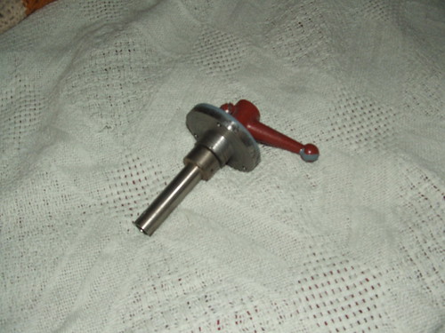
I was able to purchase a replacement control lever assembly for my 73 10EE to replace the kludge that was on there when I got it;
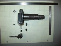
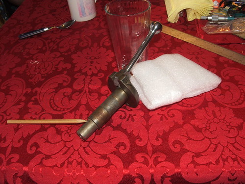
Here is the replacement as received;
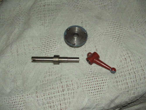
Reversed the handle to match the drawing orentation - spring works better here
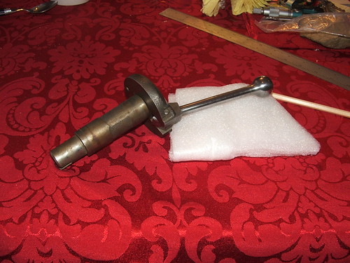
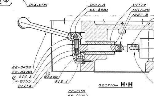
Here is the factory drawing of this asembly;
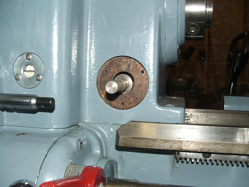
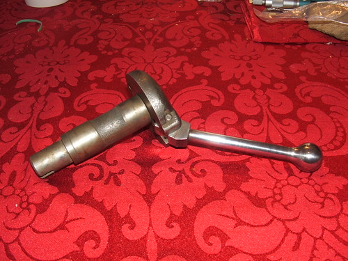
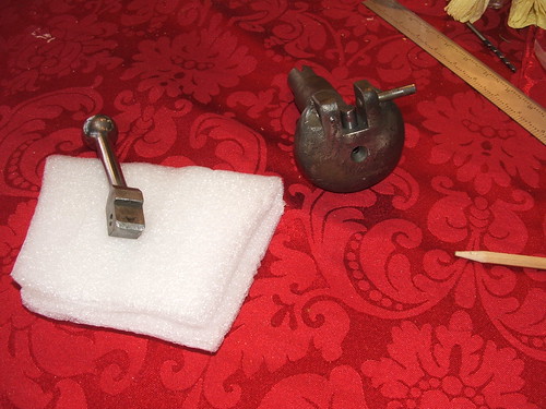
So it looks like my replacement is either a different version or has had some work done on it. In this picture the pencil points to a pin which holds the end onto the shaft (the slotted end that engages the drum switch). In this case this piece also holds on the bushing that the control turns in.
There is a hole in the front of the casting which looks like it was modified to turn the part between centers for the rework that was done;
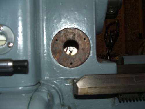
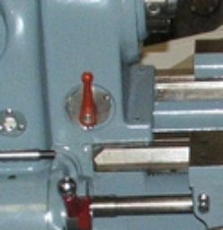
So I am missing part 83320 which is the disk that attaches via 3 screws to the headstock and is slotted for the off position (there is a pic of this in Harrys post on the wreck). OK not a big deal to make one but I want to make sure I undersatnd how the assembly should work. With what I have now the assembly would just be a press fit from the front, nothing would secure it in place as the bushing comes all the way to the face of the control
Looks like the engagement to the drum switch should be a thin section that will fit through the bushing, and the assembly is held in place by a circlip part 1011-20 which is probably a pain to install from the hole the drum switch goes in?
Is this correct? Looks like I will have to create a new 83320, modify the bushing to fit flush in the headstock, and then redo the end of the control lever. Looks to me like the thin wall section that engages the drum switch can be fairly thin as the only load should be what it takes to turn the drum switch (Pin it or loc-tite type adhesive?).
Also the interlock cam (EE-5480) is rounded a bit on the sides, per Harry's comments in the wreck it may be better to make a replacement with sharp edges? The actual part of the cam that should extend into part 83320 only protrudes about .100" eyeballing the part it looks like if I make a replacement I can also get a bit more engagement?
Thanks Paul
Here is the replacement as received;
Reversed the handle to match the drawing orentation - spring works better here
Here is the factory drawing of this asembly;
So it looks like my replacement is either a different version or has had some work done on it. In this picture the pencil points to a pin which holds the end onto the shaft (the slotted end that engages the drum switch). In this case this piece also holds on the bushing that the control turns in.
There is a hole in the front of the casting which looks like it was modified to turn the part between centers for the rework that was done;
So I am missing part 83320 which is the disk that attaches via 3 screws to the headstock and is slotted for the off position (there is a pic of this in Harrys post on the wreck). OK not a big deal to make one but I want to make sure I undersatnd how the assembly should work. With what I have now the assembly would just be a press fit from the front, nothing would secure it in place as the bushing comes all the way to the face of the control
Looks like the engagement to the drum switch should be a thin section that will fit through the bushing, and the assembly is held in place by a circlip part 1011-20 which is probably a pain to install from the hole the drum switch goes in?
Is this correct? Looks like I will have to create a new 83320, modify the bushing to fit flush in the headstock, and then redo the end of the control lever. Looks to me like the thin wall section that engages the drum switch can be fairly thin as the only load should be what it takes to turn the drum switch (Pin it or loc-tite type adhesive?).
Also the interlock cam (EE-5480) is rounded a bit on the sides, per Harry's comments in the wreck it may be better to make a replacement with sharp edges? The actual part of the cam that should extend into part 83320 only protrudes about .100" eyeballing the part it looks like if I make a replacement I can also get a bit more engagement?
Thanks Paul