What's new
What's new

Gearbox fitment

dinotom

Aluminum
Joined
Oct 25, 2016
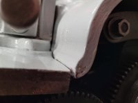
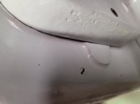
Please see the images below. This is a gearbox that Dave Erickson refurbished and was kind enough to sell to me. I believe they are from within 1-2 years of each other from a manufacturing date. These pictures are of the gearbox in place, and all the bolts fully tightened. It doesn't appear to me to be a good fit. Any thoughts or suggestions welcome. I still have the original gearbox, which has some issues, and I can and will dis-assemble and inspect and clean and refurbish, but this was a quick way for me to get the 10EE back in action.

Gearbox not flush at bottom with base

InkedIMG_1732_LI.jpg

Upper edge of gearbox not correctly aligned with headstock

InkedIMG_1733_LI.jpg

InkedIMG_1734_LI.jpg


Additionally, when putting the gearbox back together after partial dis-assembly, this threaded pin was the only thing left, and there was one threaded hole empty. AND since I didn't film or take pictures of the partial dis-assembly and there was two weeks in between, I don't have full recollection of whether this is correct.

What purpose is that pin serving anyway? When it is fully in place, it restricts the threads/feeds knob from functioning.

Threads/Feeds knob and threaded pin

Monarch_10EE_1942_Gearbox_Push-PullKnob_SidePin.jpg

Monarch_10EE_1942_Gearbox_Push-PullKnob_SidePinAndKnob.jpg
 
I don't think so. Dave was fully aware of what I was rebuilding when he sold me the gearbox. Hopefully Dave will read this and reply.
 
What purpose is that pin serving anyway? When it is fully in place, it restricts the threads/feeds knob from functioning.

The pin is an alignment pin. When original parts are lined up, they punch a hole through both parts and thread that pin in.

If that pin is to align the new gear box, to any part of your existing lathe, then i'd be shocked if it went right in. If you wanted to use it, I suspect you'd have to drill a new hole through the parts.

If you happen to have any other such pins sticking out, might be your alignment issue.

Without seeing any of the parts in front of me, you could probably get away without such pins. But I'd be checking gear lash, or whatever might be affected during that alignment, spin parts by hand, etc.
 
Last edited:
Check and see if your lead screw and feed rod are parallel with the ways.
That should tell if the gear box needs to go up or down.

Hal
 
I would not get too worried about the castings blending well together. I'm sure they were all over the map on that.

20211127_223226.jpg

20211127_223219.jpg

Mine don't look any better matched than yours.


The threaded pin....hrmmm....based on the fact that I painted over mine makes me believe I never removed it and left it in there. I;m assuming it is locating / retaining a shaft or such thing for the gear box.

20211127_223232.jpg
 
The only thing that pin does, at least through testing it by my tightening and untightening it, is it prevents the threads/feeds knob from going in and out when it is fully screwed in, once it's loosened a bit, that knob functions properly.
 
That does sound odd to me. The function of the knob should not depend on how tight or not the screw pin is. I wonder if something is now not aligned inside the box?

I don't think we have any drawings of this box...Cal?
 
That hole that you're putting the pin in should have a spring and ball for the Threads/Feeds detent I believe.
At least that what mine has but I've a CVA not a 10EE.

The pin looks like what locates the bearing spacer rings:
P5280005.jpg

P6020011.jpg

But it looks a bit long for that. I believe the 10EE has two at 180deg where my CVA only has one.

HTH

Martin.
 
I was thinking something similar that it locates a spacer or some such thing. A detent ball is a good theory as well.

Look at this....

10EE QCGB.jpg

Look at #148....I think that is the threaded pin in question.

145 is Feed Shifter Rack Pinion
146 is Feed Shifter Rack
147 is Feed Shifter Fork
148 is Feed Shifter Fork Pin

So does the pin limit the for travel/rotation? I can't picture how the fork works?
 
There is a drawing, but it's in really rough shape, sections are missing and some parts are illegible. It does show the area in question. What is shown is a setscrew, spring and plunger. The same exact parts that are used for the detent on the A-B-C selector knob. I'm pretty sure that the plunger and spring are part E4-141 (plunger) and -142 (spring). Parts E4-122 and -123 are the detent for the A-B-C selector knob. (Note that common parts, including nuts, bolts and setscrews are not usually shown on round-dial parts pictures.)

Now, parts picture E-4 in the 1942 round-dial manual is for the T-handle gearbox, not the later lever-handle gearbox. Based on very limited photographic evidence, it appears that the T-handle gearbox had a feed-thread knob that does not use the external post and notch detent system found on the lever-handle gearbox.

Lever gearbox feed-thread knob with post and notch detent (on right):
IMG_2358c.jpg

Detent notches in knob:
IMG_2375.jpg

My guess is that the feed-thread detent used in the T-handle machines was not suitable and was abandoned in favor of the post and notch system. That left the hole for the detent mechanism which was filled with the plug found by Tom. I checked my machine (a 1943 lever-gearbox round-dial) and I have the same plug that Tom has. It appears to serve no purpose, beyond filling the hole. Why they didn't simply omit drilling and tapping the hole is beyond me. I used a probe to feel for any grooves or other features on the shaft (E4-143) that a detent plunger might engage and found nothing.

Cal
 
Thanks Cal, that's exactly how mine is, notched. I'm also assuming it serves no purpose. I took that pin out of the other gearbox I have (The original one), and it had nothing but the pin in the hole too.
 
Hi Tom, I can't help with your questions, except one: the gearbox in question came from a 43 parts lathe. I had some of the same issues installing a square dial gearbox on a 49 mfg. lathe earlier this year, i.e. the rough castings did not align in front. I think they were ground down to match after they were assembled, so it is just a cosmetic issue. The machined surfaces are a different matter; they should fit.

I'm glad to see you are making progress.


Back
Top