shapeaholic
Stainless
- Joined
- Oct 14, 2003
- Location
- Kemptville Ontario, Canada
Hello all,
I thought I’d post some follow-up to my Hendey lathe bed refurb project.
As you may remember I was originally planning to scrap the center of the bed and use the “Beckley23” method to fix the carriage ways.
After some torturous work, I came to the conclusion that I probably would be 100 before I finished that plan, so I decided to get the bed professionally ground.
Scroll ahead a couple of weeks,
I had some time off owing from work, so I figured just as well now as ever, and contacted Kellar Machine Rebuild (KMR) in Kingston Ontario about getting the work done.
The owner, Mike Kellar told me that he could fit me in toward the end of the week and, if necessary over the weekend.
As shipping was going to be an issue I decided to load the bed in my truck and drive the 8hrs and wait for the job to be done, then haul it home. (This was actually cheaper than shipping)
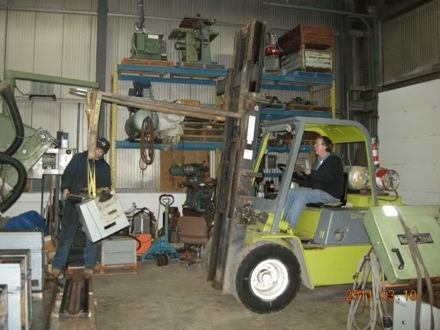
On last Wednesday afternoon ( March 9,2011) I arrived at KMR and met Mike and his nephew Jason Kellar, who is his helper/trainee. I got the tour of the shop and we discussed how things might happen.
We unloaded the lathe bed and got to work, BUT not on my project.
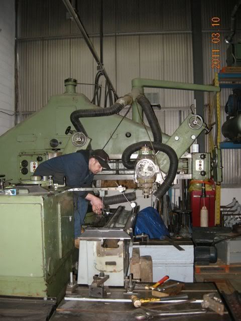
Mike told me that the bed had to warm up until at least the next morning, so I got to watch them grind the ways on a milling machine table that was set up on the big WMW slideway grinding machine. They had set up the saddle next to it and were going to grind the slide in the same setup ( sorry I didn’t get a picture)
As a side bar to all this, when I spoke to Mike on the phone, I commented about scraping the bed. “You know how to scrape?” he says. Yes I knew a little about it. So he asked me to bring some “stuff” and teach Jason some scraping.
This was a bonus as it would give me something to do while I waited for the bed, and allow me the opportunity to observe the work being done on my project.
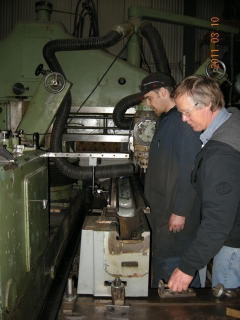
Anyway, I put on the overalls and Jason and I got to scraping while Mike worked on the mill table. The scraping lessons progressed intermittently through out the whole time I was there.
Thursday morning I showed up at KMR at about 8:30 to find the guys still doing stuff other than my lathe bed. (wait in line Pete ;-)) But that was OK as I was able to watch them grind some parts for a Colchester that a customer had “fixed” using a magnetic chuck on a surface grinder. What a mess that turned out to be. It will be nice once KMR is done with it, but that owner didn’t do his machine any favors.
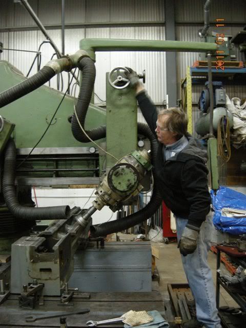
Around 10:30 we started loading the Hendey bed on the machine.
Mike set it up on 3 points and leveled it with a Starrett master precision level. He then set up a couple of dial indicators and adjusted the bed straight with the grinder to near 0-0.
This process took the best part of 1.5 hrs.
After lunch Mike started by grinding the tops of the carriage ways. I asked him to make sure that they turned out as level as possible as I wanted to use it to level the machine later.
He then set up to grind the Headstock seat/tailstock slide. This is the one I had partially scraped. It turned out to be pretty good, within a couple of tenths, which was pretty gratifying. He had to take another couple of thou off the remove all the damage.
Work continued until quitting time and we adjourned for the evening.
Next morning work started on the front carriage slide.
I was most interested in this as this one had the most wear. I had measured it as being between .007-.010” worn.
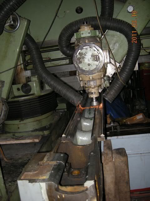
WELL…. By the time Mike removed the damage and got it straight he had removed nearly .040”.
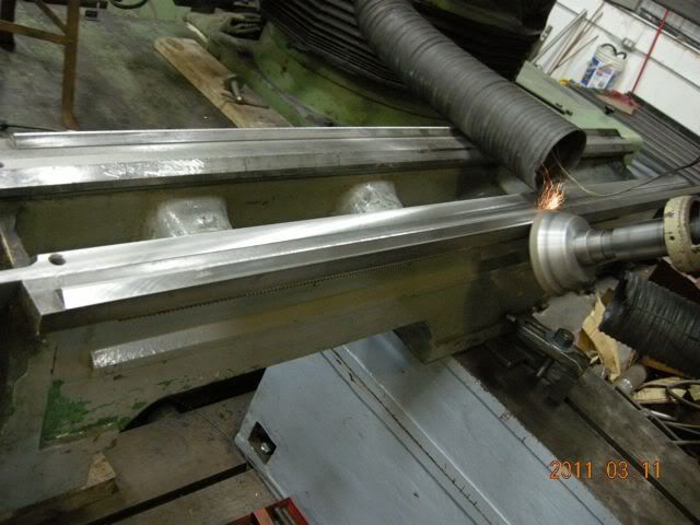
look closely just to the left of the grinding wheel and you may be able to see the damage
This was much worse than I feared! The rest of the bed was not near as bad, although there was some twist that made for a little extra work.
All in all the grinding took close to 14 hours. Mike ground 12 surfaces. All are now straight and parallel within .0001” as they were all ground on the same setup.
Mike took particular care to ensure that the horizontal surfaces were level and that everything had a nice fine finish. He also ground a couple of surfaces that I hadn’t considered, like the bottom of the tailstock slide, and the bottom of the rear carriage way as these have parts that clamp up on them.
I have to say that I am very pleased by the service I received! Mike’s willingness to accommodate my schedule and his patience and tact in dealing with my lack of knowledge and preconceived ideas on how I though this should turn out is to be commended.
I paid approximately $1800.00 plus taxes. This was about equal to another quote I'd gotten and $600 cheaper than the big shop in Toronto.
Considering the amount of work done I think this is good value. It would have been an impossible chore to do by hand, and with every pass of the grinder I had more and more admiration for Harry Bloom!
I thought I’d post some follow-up to my Hendey lathe bed refurb project.
As you may remember I was originally planning to scrap the center of the bed and use the “Beckley23” method to fix the carriage ways.
After some torturous work, I came to the conclusion that I probably would be 100 before I finished that plan, so I decided to get the bed professionally ground.
Scroll ahead a couple of weeks,
I had some time off owing from work, so I figured just as well now as ever, and contacted Kellar Machine Rebuild (KMR) in Kingston Ontario about getting the work done.
The owner, Mike Kellar told me that he could fit me in toward the end of the week and, if necessary over the weekend.
As shipping was going to be an issue I decided to load the bed in my truck and drive the 8hrs and wait for the job to be done, then haul it home. (This was actually cheaper than shipping)
On last Wednesday afternoon ( March 9,2011) I arrived at KMR and met Mike and his nephew Jason Kellar, who is his helper/trainee. I got the tour of the shop and we discussed how things might happen.
We unloaded the lathe bed and got to work, BUT not on my project.
Mike told me that the bed had to warm up until at least the next morning, so I got to watch them grind the ways on a milling machine table that was set up on the big WMW slideway grinding machine. They had set up the saddle next to it and were going to grind the slide in the same setup ( sorry I didn’t get a picture)
As a side bar to all this, when I spoke to Mike on the phone, I commented about scraping the bed. “You know how to scrape?” he says. Yes I knew a little about it. So he asked me to bring some “stuff” and teach Jason some scraping.
This was a bonus as it would give me something to do while I waited for the bed, and allow me the opportunity to observe the work being done on my project.
Anyway, I put on the overalls and Jason and I got to scraping while Mike worked on the mill table. The scraping lessons progressed intermittently through out the whole time I was there.
Thursday morning I showed up at KMR at about 8:30 to find the guys still doing stuff other than my lathe bed. (wait in line Pete ;-)) But that was OK as I was able to watch them grind some parts for a Colchester that a customer had “fixed” using a magnetic chuck on a surface grinder. What a mess that turned out to be. It will be nice once KMR is done with it, but that owner didn’t do his machine any favors.
Around 10:30 we started loading the Hendey bed on the machine.
Mike set it up on 3 points and leveled it with a Starrett master precision level. He then set up a couple of dial indicators and adjusted the bed straight with the grinder to near 0-0.
This process took the best part of 1.5 hrs.
After lunch Mike started by grinding the tops of the carriage ways. I asked him to make sure that they turned out as level as possible as I wanted to use it to level the machine later.
He then set up to grind the Headstock seat/tailstock slide. This is the one I had partially scraped. It turned out to be pretty good, within a couple of tenths, which was pretty gratifying. He had to take another couple of thou off the remove all the damage.
Work continued until quitting time and we adjourned for the evening.
Next morning work started on the front carriage slide.
I was most interested in this as this one had the most wear. I had measured it as being between .007-.010” worn.
WELL…. By the time Mike removed the damage and got it straight he had removed nearly .040”.
look closely just to the left of the grinding wheel and you may be able to see the damage
This was much worse than I feared! The rest of the bed was not near as bad, although there was some twist that made for a little extra work.
All in all the grinding took close to 14 hours. Mike ground 12 surfaces. All are now straight and parallel within .0001” as they were all ground on the same setup.
Mike took particular care to ensure that the horizontal surfaces were level and that everything had a nice fine finish. He also ground a couple of surfaces that I hadn’t considered, like the bottom of the tailstock slide, and the bottom of the rear carriage way as these have parts that clamp up on them.
I have to say that I am very pleased by the service I received! Mike’s willingness to accommodate my schedule and his patience and tact in dealing with my lack of knowledge and preconceived ideas on how I though this should turn out is to be commended.
I paid approximately $1800.00 plus taxes. This was about equal to another quote I'd gotten and $600 cheaper than the big shop in Toronto.
Considering the amount of work done I think this is good value. It would have been an impossible chore to do by hand, and with every pass of the grinder I had more and more admiration for Harry Bloom!
 I must be dense this morning.
")
 As far as the tailstock is concerned I seem to be the only one that has had success using Moglice on the bottom. I could barely move it, as the contact was almost a "wring" to the ways.