What's new
What's new

GE DC300 driver on Monarch, FL04 FlOSS loss of field current

Bordaco

Plastic
Joined
Sep 24, 2007
Location
Bolivia - Cochabamba
Hi, I know this is for lathes, but I have a Monarch VMC150 whit a DC300 spindle drive, and sundendly come in error (afther working two years whit out problems) whit error code LED :

000100 FL04 FlOSS loss of field current (L,T)

Acording to monarch thec support is:

- CFU1, 2 or 3 on Power supply card blown
- 1PL disconnected or damaged
- Field grounded
- Field lead connections
- Open field circuit
- FLDLS set to high
- FC gain jumper set wrong
- Field regulator gain too low- adjust BFLPG

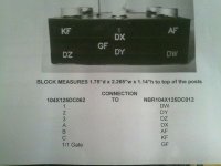
We dont have manuals for this drive, and I think is the diode powerpak (Gentron Powertherm 104X125DC12ST), The digital tester tell me that is bad, but i not shure, because I don't have a power diode test equipment.

Any coments?, sugestions, experience similar problems?.

All is welcomed.

Regards.

Boris, From Bolivia South America

PD, there is no GE service here
 
Well, if it was working for 2 years, then suddenly quit, you can probably rule out incorrect settings or jumper positions.

Can you disconnect the motor field leads from the drive, and check field resistance and insulation?

What kind of readings are you getting on the "diode powerpack"? Semiconductors usually fail shorted, rather than open. Is this just a diode bridge, or does it contain SCRs?

If it has failed shorted, check for a fuse upstream of it that has blown.
 
Hi Boris, there is a ge dc300 for sale on ebay, has been there for months, and it might be the same one you have, because it is much larger than the dc300 used for a 10EE.

You can contact a GE consulting engineer. The hourly rate is reasonable, and if you get one that knows the control, he can provide a lot of useful info. Lathehand did that to get information on how to setup the dc300 for his 10EE.

-Dave
 
Hi to all, and thanks for replay.

No fueses blow, I check all, the inpedance on the field are 100 homs, the motor plate says, 95 homs, I thik is ok, also is not grounded, so the insulation are ok.

Not boody touch the jumpers or hardware settings, anyway I dont have a manual to check that, and GE dont offer a online manual. some one have a manual for this driver?

Yes, ebay, is an option, driver cost 2500$,(used) plus 500 or more on shipping, (is heavy) and no warranties of work, maybe they need to be reprogramed or exchange the control board.

I was hoping that somebody have the same or similar and tell me the values of the diode pack.

The digital tester in diode mode show the firts diode 0.5, and the rest are 0L (open). but somebody tell me that digital tester on power diodes don't work.

This is a DC300 500Vdc for 15hp 28amp

Boris
 
By "digital tester", I assume you mean a DMM with a diode test function?

Can you post a picture of the diode block you are trying to test? Is it just a rectifier bridge, or are there SCRs involved?

A standard diode junction should show a voltage drop of .6-.7 V when forward biased, and an open circuit in the reverse direction. A DMM diode test will not find things like a diode that breaks down under high voltage or high current, but they work just fine to find 99% of failures.
 
Here are some pictures,
1º is the original part in the driver
2º is a schematic of the replacement model
3º is the conection pin asigment

I just don't want to buy a replacement, just to find that there wasen't the problem, because I will be waisting time, at least 1 week for the delivery of the part.
 

Attachments

  • 23082010257.jpg
    23082010257.jpg
    15.9 KB · Views: 445
  • 27082010259.jpg
    27082010259.jpg
    16.7 KB · Views: 763
  • 27082010260.jpg
    27082010260.jpg
    17 KB · Views: 549
OK, it looks like that module houses 3 diodes for the field rectifier, and an SCR for control. First step in testing is to disconnect ALL wires from the module, to completely isolate it from the rest of the drive circuitry. Make sure that you are using the "diode test" function on your meter, and not a standard resistance range.

Testing the 3 diodes is simple enough. Connect the negative meter lead to the common cathode terminal (DX). The positive meter lead then connects to the 3 anode terminals (DW, DY, DZ) one at a time. Each should show a voltage drop of .6-.7V. Then reverse the meter leads and retest. All 3 diodes should show as "open".

Testing the SCR is a bit more involved, and may not be possible with just a DMM. Connect the positive meter lead to the anode (AF) and the negative to the cathode (KF). Should show an open circuit. Leaving the meter leads connected, use a wire to short the gate terminal (GF) to the AF terminal. The SCR should "turn on", and the meter will show a .6-.7V drop. The SCR *should* remain on after the GF jumper is disconnected, but this will depend on the test current of your meter and the minimum holding current spec on the SCR. Reversing the meter leads should show an open circuit. These simple tests should be able to detect a shorted SCR, which would be the most common failure mode.

Make these tests, and let us know what you find.
 
Definitely, is the diode pack, I ordered a replacement part, so as soon I get the part intalled an working the machine I will close this thread, thanks for all the help.

REgards.


Back
Top