What's new
What's new

Looking for help- 10EE steady/follow

DaveKamp

Titanium
Joined
Oct 3, 2004
Location
LeClaire, Ia
Hi all!

I don't have a steady or follow-rest for my '42 EE. I know another forumer is in the same situation, and there's undoubtedly more.

While these things come up for sale every-so-often, it's obvious that there's many more machines than steadies and follows... and there's much more demand for originals than my hobby budget allows (I could be spending the difference on another machine, or propane to heat the shop, or a rotary indexer, or a...

So anyway...

Is there anyone who'd be willing to help (either by dimensioning, or lending one of each) me pattern out a steady and follow, so that we can CAD and cutpath blanks for making nice rests for these buggers?

If you're willing, drop me a note... I'll pay for any expenses,etc., get the necessary dimensions, photos, etc., and get 'em returned to you in shortest-possible timeframe.

Thanks!
DK :-)
 
Still bobbin'...

Hi Cal, Tom, Beck-

I did get one email... I was swamped with work, so I didn't respond, but one guy had a steady/follow set for sale... and I had better padding-in-my-pockets, I'd buy 'em just to pattern 'em out.

What initiated this... was a nice chat I had with Jim Bergstrom (I bought his horizontal mill).
He's in need of a steady-follow pair, too, and if I find and draw up the shape, he'll make up the CNC cutpath, load metal into a center, and have it chew out the major pieces to make a 'kit'.

Again, if I had a much more flexible budget (how's that for mincing words??) I'd buy the set, and plot 'em all out, and we'd have Jim making the modern CNC version... alas, I've got other irons-in-the-fire (a big L&S, a pole-barn needing concreten, a machine shop needing concrete, and about 21,493 other things here that need both attention and money... both of which I have less-and-less of each day (sigh)... so the things that 1) scream the loudest and 2) are quickest to resolve) get the most immediate attention...

But the offer's still out there...

And I got my boom-sprayer done today, so at least the gnats won't be so bad tomorrow (should be a bit less 'alive' today, anyway).

DK :-)
 
No idea yet...

No idea on price yet, but Cal has offered to let me borrow his rests to pattern 'em out for CNC cutpath definitions.

I'll be working with John Bergstrom getting the data from the workbench to his machinery. Once that's done, I'm betting that John will be able to calculate the costs pretty handily... and I'm certain he'd make it reasonable for all.
 
Dave, I assume you have a round dial? Square dial rests are 1/2" taller.

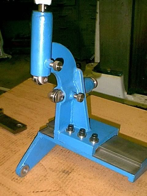
It would be cool to make a copy of the square dial follower rest, reduced in height 1/2" (the standard model that attaches to the saddle with bolts on both sides of the cross slide) - it is a lot sturdier and simpler to adjust than the round dial follower rest.
 
That a really nice job, Harry!

fr13.jpg


I like the lateral adjustment! What's the plunger consist of?

Cal
 
It's all HR or CR steel, except the knobs and jaw locking screws, they're 304. The jaw screws are Stressproof. I've got a set bronze tipped jaws for all of the FR's.
I may have to look for cam followers, like the type used on W&S roller turners, to replace the ball bearings. I had a chatter problem a couple of weeks ago.
Harry
 
Thanks Harry. Do you have any pictures of the plunger out of the rest. I curious about how it works: Does the screw drive in both directions or is it spring loaded? Is there a keyway to keep it from rotating?

Cal
 
If you look at the horizontal jaw, just behind the bearing pin is the start/end of the key way. The locking screw has an extended tip for the key. No springs, strictly screw operated.
If you are designing a FR, allow for the future? addition of a DRO, it's a PITA to cut one apart and add additional length. Don't ask how I know.
Harry
Thanks Harry,

What keeps the screw from backing out when you extend the plunger?

Good tip on the allowance for a DRO.

Cal
 
The screw has 3 diameters, IIRC. The threaded section is turned from larger diameter stock and the knob section, which is smaller than threaded section, in between is the stock diameter. The knob is pinned on after assembly in the jaw bore.
Harry
 
Harry- more photos...

Harry-

I like that design, definately more robust than the 10EE standard follow... Cal says it'd be a better one to dupe than the original.

Can you photo from all sides, scratch and sketch with dimensions for me?

I'll make one to fit a 10EE, and then dimension it for DIY's... perhaps we can find a CNC'er who'd be willing to cut the pieces for a kit...

And if you happen to have any pix of it mounted to the machine, please show!
 
Last edited:
photos's of cnc swiss style steady rest/ guide bushing

I think it was Cal who expressed interest in seeing how a cnc swiss holds the stock. The photo editor is still downloading, but I will link to pics on photobucket. The square post in front of the turrets is a bearing floated giude bushing with a guiode collet. It does not move with the x axis and is set to allow the stock to slide through it yet not be loose. tools are all 2mm in front of the guide bushing and all turning is done in 1 pass whenever possible.

http://img.photobucket.com/albums/v185/willeo6709/citizen21.jpg
http://img.photobucket.com/albums/v185/willeo6709/citizen1.jpg
 
Dimensions on the above FR would be worthless, that FR is for a 16" CY and is about 4 times larger than what would fit on the EE.
Designing a FR is pretty easy. You need some basic measurements; where is the spindle center in relation to the mounting points on the carriage. Measuring the carriage is the most difficult part. In your design make sure you allow for a possible future addition of a DRO, I had to "stretch" 2 of these FR's. Allow for clearance when designing around the cross slide, especially the bolts that stick up at the nut. You don't want the bolts catching, or the cross slide rubbing on the FR.
One thing I try to incorporate in my designs is "keying" the various members with slots for alignment when welding. It takes a bit more work, but pays off in the end.
One word of advice; I would stick with the basic Monarch jaw design for the EE, and use a burn-out for the upper FR frame.
The only finish machine work I did before welding were the dovetails, and the jaw bores in the guides, which needed work after welding, all the rest was done afterwards.
Harry
 
Here is a steady that I cobbled together from scrap. The telescoping jaws were copied from an import that I adapted to another lathe.
I didnt bother to make it hinged, easily done though. This has 1/2" left hand screws, so when the knobs are turn clockwise, the jaws extend.
The standard steady has small capacity, this one has 5 1/4" for sleeves and other items.
When I make items like this from free metal, I find it not worth while to make a drawing as it has to come out of given size pieces, just a note pad.
Click on photo to see how bad I weld!
http://s170.photobucket.com/albums/u265/donsmonarch10ee/?action=view&current=ljuly2005bike001.jpg


Back
Top