What's new
What's new

M-G 10EE with exciter modification, ran with NO EXCITER.

Glock34

Plastic
Joined
Jul 30, 2019
Location
Connecticut, 'Merica
Hey All,

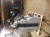
I picked up a 10EE a couple of weeks back, and I have a few questions.
Here's what I know about this particular unit.
It is a round dial, M-G machine, MFGR'S # is 25476, build date: 7-1944.
It has ELSR, (most of) a taper attachment, and an Accumulating Cross Feed Dial.
I purchased it from a manufacturing company that used it in their tool room. I was told that it was removed from service because it would surge, but otherwise worked fine. It was wired to 480v 3ph.

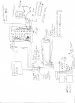
I have already learned a ton of stuff reading through many threads here, but as is my luck, this unit has a couple of modifications that are baffling, as well as a potentially dangerous modification. I will attach a couple of drawings of the wiring I've traced out so far that will show the mods I need help with.

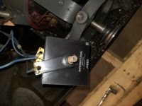
First, the dangerous mod. The AC contactor, heaters, etc. have been completely bypassed by a push button on/off switch. Questions: Is this contactor assembly available in it's original form, with a 220v coil? Is there a suitable replacement available that would fit under the cover? Could the overload heaters/switch just be replaced by circuit breakers?

Next is the input power. This was plugged in to 480 3ph, but that was run directly to two, (single phase), transformers, and the wiring on those is, for lack of a better word, goofy. (See attachment.) Has anybody ever seen transformers wired like that? I do have to say that I Googled that model transformer, but could not find an internal diagram for it, so internals on my drawing are based on my experience with transformers. It could be wrong, but even if it is, well, just look at the wiring!

Last, (for now). There is NO EXCITER! It has been replaced with a 440-115 transformer, a big ol' resistor, & a fuse! I have been unable to find this type of mod anywhere. Has anyone seen/done this? Is this a workable mod?

Possibly the biggest problem I have is that I cannot test the machine due to no 480v 3ph power, and need to sort this stuff out so I can decide what the best way to go would be. Should I trash the whole electrical system & go with a single phase 220v motor? Assuming I could convert to 220v, build a phase converter? Go with a VFD? Convert the motor to single phase via the Steelman method, (again if possible, no extra wires from the M-G windings)? Any other suggestions?
Input_Xformers.jpg
Thanks in advance!
Ted
 

Attachments

  • Wiring1.jpg
    Wiring1.jpg
    90 KB · Views: 80
I think what you have there are a pair of transformers wired to "buck" the voltage down to a lower voltage. Please post a photos of:


  • the terminal panel on the motor generator (MG)
  • the tag on the MG
  • the DC control panel next to the spindle motor
  • the tag on the spindle motor
  • the components related to the exciter replacement

I would also appreciate some overall photos of the machine, including the accumulating cross-feed dial

Cal
 
Additional pictures needed:

Good photos of the inside of this: The AC contactor, heaters, etc. have been completely bypassed by a push button on/off switch.

The nameplate info and pictures of the connections on these: This was plugged in to 480 3ph, but that was run directly to two, (single phase), transformers,

And good pictures of this, including nameplate info: NO EXCITER! It has been replaced with a 440-115 transformer, a big ol' resistor, & a fuse!

Bill
 
Cal,

I too thought the transformers may be for bucking power, but the 10EEs were 440/220 volt machines, and one of the input legs actually bypasses the transformers. Doesn't seem to make sense to put two lines somewhere between 220 & 440, and leave the other, but then I don't know a lot about 3 phase.
I don't have a pic of the tag on the spindle motor, but here are the rest of the pics you asked for, and some others. (Actually not sure any pics will show up, I think I broke the internet again.)

Thanks,
Ted
 

Attachments

  • 20190725_193245.jpg
    20190725_193245.jpg
    89.7 KB · Views: 213
  • 20190725_201313.jpg
    20190725_201313.jpg
    94.5 KB · Views: 211
  • 20190722_172426.jpg
    20190722_172426.jpg
    84.8 KB · Views: 89
  • 20190725_192917.jpg
    20190725_192917.jpg
    95.3 KB · Views: 62
  • 20190729_170306.jpg
    20190729_170306.jpg
    91.4 KB · Views: 76
Hey Bill,

Here are some pics. The contactor, etc. is still in place as you'll see, just jumped out. The Jefferson nameplate is for the transformers on the input side, there are two as per my diagram. I don't have pics of the wiring, but my diagram is accurate. The pic of the red tag is for the transformer that replaces the exciter, and the best pic of that I have I posted already in reply to Cal.

Thanks,
Ted
 

Attachments

  • 20190722_172529.jpg
    20190722_172529.jpg
    93.5 KB · Views: 73
  • 20190722_172556.jpg
    20190722_172556.jpg
    86.3 KB · Views: 72
  • 20190725_192645.jpg
    20190725_192645.jpg
    95.1 KB · Views: 57
  • 20190719_184239.jpg
    20190719_184239.jpg
    94.6 KB · Views: 76
  • 20190719_184321.jpg
    20190719_184321.jpg
    90 KB · Views: 55
Cal,

I too thought the transformers may be for bucking power, but the 10EEs were 440/220 volt machines, and one of the input legs actually bypasses the transformers. Doesn't seem to make sense to put two lines somewhere between 220 & 440, and leave the other, but then I don't know a lot about 3 phase.
I don't have a pic of the tag on the spindle motor, but here are the rest of the pics you asked for, and some others. (Actually not sure any pics will show up, I think I broke the internet again.)


262309d1564626753-m-g-10ee-exciter-modification-ran-no-exciter-20190725_201313.jpg


262308d1564626410-m-g-10ee-exciter-modification-ran-no-exciter-20190725_193245.jpg


Thanks,
Ted
OK. I see what's going on. That's a 550 VAC only motor generator. It's single voltage, with only three wires coming out of the AC motor itself. The transformers must be configured to boost 480 VAC up to 550 VAC. I doubt you have enough transformer there to boost 240 up to 550.

Cal
 
Last edited:
I didn't notice that the motor is 550 volts. I thought they were 440 or 220 only. Any idea why? I've never seen 550 volts anywhere.
Well, that narrows down my options...and raises the cost. :(

Thanks,
Ted.

Hmm, If I figure out the speed that motor should go, and use the right ratio pulley to the front of it, then hook up the PTO of my John Deere to it...would that make it an "engine" lathe? LOL.
 
The 2 transformers are used to BOOST the 440 to 550 with an open delta configuration.

The item below the red label transformer is a bridge rectifier that will produce DC from AC

The push button switch probably is a manual starter with heaters for overloads inside. It was used because the coil on the factory starter has a burned out coil.

The MG turns 3600 RPM.

Bill

Correct on all counts. The transformers would barely supply 3 hp by themselves if you had a very efficient motor but in this configuration they are only supplying 1/5 of the power, well within their capacity. Boosting 220 to 550 is a bit tricky. You would have to connect one of the 220V primarys to the line with the other in series to get to 440, then hook the 110V windings in series with that to reach 550. that would supply 3/5 of the power from the transformers, within reach. Incidentally, these are standard line transformers, available used, surplus, etc.

The rectifier doesn't seem to have any filtering but the field inductance is probably enough.

If the push button has overloads, it would do. If not, you can probably get a replacement coil.

Bill
 
Hi Bill, AKA hitandmiss

Thanks, good info about the transformers & rectifier, which I looked at today and discovered was, in fact, a rectifier, not a big ol' resistor as I had earlier thought. I opened the box for the push button switch when I was going over the machine, and it is just a switch, no heaters, circuit breakers, or other safety devices of any kind. That's why I referred to it as the dangerous mod.

Thanks,
Ted
 
Hi Bill, AKA 9100

(Geez, so many Bills here, story of my life! LOL. But I am very grateful for all the Bills here.)

I work on electrical and mechanical stuff daily, forklifts, scissor lifts, related battery chargers, etc., and like to engineer stuff mostly as a hobby, but transformers are not something that I do any engineering with, only repairs, so I'm a little lost when dealing with power conversions like this. Gonna take a bit of thinking to understand what you wrote. The only question I have about it is can this be done with single phase, because that is all that is available to me. Right now I'm leaning toward trying to find a 440/220 MG setup & converting via the Steelman method as the least costly and "offensive" way of doing it. I tend to be nostalgic, and really like the way the controls work as I understand them.

Thanks,
Ted
 
Perhaps one of our Canadian members might chip-in?

ISTR 550 VAC is on their menu, and for-sure quite a few round-dial MG 10EE were sold to Canadian defence firms, War Two.

PTO? Yes, if-come. You can even run it off a waterwheel or a coal-fired steam engine if you want to do badly enough. It needs somewhere between 4 1/2 and 6 HP at the input. The Ward-Leonard or "VS Drive" is smooth enough, just not all that efficient, energy-conversion-wise, by the time it gets power to the spindle, and then.. it may be called upon to run-MG for significant periods whilst spindle drive isn't even active at all, let alone "in the cut".

As to cost ... up to my nips 'til I get Wife & M'in-Law on a plane back to HKG around 24 hrs hence, but let's see what other options PM community might conjure-up besides transformers.

A coal fired steam engine? Geez, how about moving up a couple of centuries, a natural gas fired steam engine would be much more environmentally friendly! LOL!!!
 
More pics.
The tag on the spindle motor.
The end of the rectifier, which I incorrectly identified as a resistor earlier.
The back of the lathe.
The taper attachment.
The transformers.
 

Attachments

  • 20190801_183850.jpg
    20190801_183850.jpg
    93.3 KB · Views: 48
  • 20190801_184417.jpg
    20190801_184417.jpg
    82.9 KB · Views: 48
  • 20190719_184303.jpg
    20190719_184303.jpg
    97.1 KB · Views: 44
  • 20190722_172659.jpg
    20190722_172659.jpg
    97.4 KB · Views: 50
  • 20190722_172846.jpg
    20190722_172846.jpg
    91.9 KB · Views: 47
... The only question I have about it is can this be done with single phase, because that is all that is available to me. Right now I'm leaning toward trying to find a 440/220 MG setup & converting via the Steelman method as the least costly and "offensive" way of doing it. I tend to be nostalgic, and really like the way the controls work as I understand them.

Thanks,
Ted
If you can get a 220/440 MG set for a reasonable price, that's the way to go, but I don't think that the "Steelman" conversion is the least costly solution, especially if you don't have the skills to modify the guts of the motor yourself.

There are lots of us running motor/generator 10EEs from single phase 240. Most of us use a "rotary phase converter" or RPC. They are brutally simple, just an ordinary 240/480 3-phase motor (7.5HP is a good size), a starting circuit and a set of run capacitors. The starting circuit is just a potential relay and one or more starting capacitors. 3-phase motors can be started in the same fashion as a 1 HP single phase motor (which also uses a starting capacitor). The 3-phase motor is called an idler motor and together with the run capacitors, can provide "good enough" 3-phase power for all the 3-phase motors in your shop. The run capacitors are usually tuned a bit to get the artificial third phase to about the right voltage. You can pick up a used 3-phase motor locally for about $10 per HP. Outfits like WNY Supply sell 7.5HP RPC panels for under $200; WNY has RPC kits for under $100.

Another option is to run the MG using a so-called "static phase converter", which is nothing more than the motor start portion of an RPC. There are several guys using SPCs with no issues. Be aware that your standard Phase-a-matic type SPC typically doesn't have run capacitors and they can be a problem when the MG's loading changes. That's easy enough to fix by just adding a pair of run caps.

You also have the option of keeping the DC spindle motor and replacing the MG with electronic controls. The least expensive option there is using a simple, non-reversing DC controller to provide power for the DC spindle motor's armature, in place of the MG's DC generator. A simple rectifier, like the one you currently have, supplies power to the existing DC control panel and the spindle motor's field. The existing DC control panel continues to control reversing, anti-plugging, field acceleration, etc., and the existing Ohmite rheostats continue to provide the field weakening. KB Electronics has a 3HP DC controller that's available on Amazon for a little over $100 (link). That drive will only get the armature up to 180 VDC, but that may well be enough for what you need to do. (IIRC, hitandmiss Bill is using a KB drive on one of his 10EEs). There are much more exotic DC controller solutions, but they can get pretty expensive and complicated.

Cal
 
Least TIME wasted is not the least costly in money, but works well:

Given:

- The turbine-smooth, "servo-like" Dinosaur-Current final-drive motor is the only 'sacred' part and that is nominal 230 VDC.

I discard every switch, relay, contactor, and inch of wire to save only that precious (literally, at $12,000 MSRP, new) DC motor.

One of the two MG's I have is committed to another member - ever I get my old laptops's email system recovered and restore knowledge of WHOM.

:(

"See Post #9". Wife is now safely airborne, do you want an entire "normal" MG rig?

The other - a 1944 "round dial" MG is still available. They are heavy buggers to ship. Fastenal probably the cheapest. DC panel can come with it. I've already given the first one to another member. I can palletize. Or load - your wehicle. Under 400 lbs IIRC, so at least a hatchback, van (or trailer) if not p/u truck. Connecticut is a same-day out and back to close to Dulles airport for the bold. Overnight rest more comfortable "inland" routing for we older farts.

The reason they ARE surplus is the "nuclear option" being exercised:

Two used Eurotherm/Parker-SSD drives, (1 Ea. 4Q 514C-16 + one ea. of 1Q 506, 507, or 508), used boost transformer(s), new Hammond ripple-filter (a 20 mH 20A "Choke").. -

Out-of-pocket probably $2000 to do as several of us have done. Add another $1500 or so if using NEW Parker-SSD drives. Proven performer on MG-era 3 HP through Module Drive 5 HP.


Hey Bill,

Seriously thinking of taking a drive down. Would next Saturday work for you?

Thanks,
Ted


Back
Top