What's new
What's new

Metric Threads

beckley23

Titanium
Joined
Feb 19, 2003
Location
Louisville, KY, USA
Ever since I got finished with the differential indexing attach for my dividing head, I've been considering making the metric gears for one, or two, of my lathes, mainly the CK or the Series 60. I'm looking through the possibilities with the SE 60 set that Monarch shows, and there are a couple of gears that will give the following pitches; .325, .65, 1.3, 2.6, 5.2, & 10.4 for one gear, .4062, .8125, 1.625, 3.25, 6.5, & 13 for another gear. These pitches are shown on the Monarch pitch chart, and are the only pitches shown for these 2 gears. From what I have found in Machinery's Handbook, these pitches aren't listed, or am I missing something.
Harry
 
Not a clue, but I've only seen the standard ones, plus a few oddball fine threads used in the optical industry. Consider though that there are all sorts of possible pitches you can cut with given gears. Maybe they just listed the possibles for those gears, even if they weren't standards. Give me any arbitrary pitch and I'll give you the compounds necessary to cut it near dead on!
 
If you order the metric change gear set from Monarch, these gears are part of the set, and the pitches listed are on the chart.

I went through MH and listed all the metric pitches I could find, those pitches are not listed, with the exception of the 1.3 Lowenhertz.

I think it comes down to this; Are there some specialty pitches that aren't listed, that are in use somewhere, or are these pitches that are no longer "standard" in todays world, but used long ago.
Harry
 
I think it comes down to this; Are there some specialty pitches that aren't listed, that are in use somewhere, or are these pitches that are no longer "standard" in todays world, but used long ago.

Sure - I think .65 has been used somewhere, the metric fine pitch threads took a real long time to standardize.

Found one: Progress System #13 is .325mm pitch. You might be safe in ignoring that one.
 
1939 MH Pg 1293 lists pitches used by the French. 3.25 and 6.5 are listed there.

The British BA threads use some real odd pitches. Along with a PA of 47.5 degrees!

Nothing in the gear world would use circular pitches as a standard.
 
Hi Harry,
I imagine it would be super easy to adapt the perl program I wrote for 10EE Round Dial Metric gearing to your other models of Monarchs. The program is predicated on no tranposition: i.e. it uses the standard gear train and finds the combinations using off the shelf gears from Boston Gear to do a long list of metric pitches.

Although a transposing gear will give exact metric pitches, the transposition gearing at least for the 10EE does not use off the shelf gears (it uses 32DP instead of the easily availabe 16DP gears already in the gear train). Using 16DP gears without transpostion, the combinations that the program come up with have an error or something like .02%, so they are pretty good, and they are not limited to the pitches that the transposition set provides. Anyway, to adapt the program what is needed is a description of how the gear train works. For example, on a 10EE, with 24 tooth stud gear and 48 tooth box gear, in position A the threads available are 12,13,13.5,14,15,16,18,20,22 & 23. Position B doubles those and position C doubles them again. Also, the largest gear I could add in the stud position is about 55 teeth, which limits the combinations the program can try. Smallest is about 20 teeth.

If you can give me a similar description of the threading on the Monarchs you want to add metric threading to, I can modify the program accordingly and email you a list of possibilities.
 
After 50+ years of "beating" on motorcycles (and cars) that use metric threads, I have to tell you I don't recall ever seeing a thread with any of the pitches you listed in your OP. It may be that Monarch listed these pitches in the interests of "complete disclosure" because they result from using the gears they supplied.
 
Dave,
I appreciate the offer. I'm attaching 9 pictures of the charts and the way I got there for the 12" CK. These were figured out in 2007, as a curiousity, as well as the ones for the CY. I did get the parts list from Monarch, but no charts, and just wanted to see where they would take me. I'm still on the fence about doing this, as I don't get calls for metric threads very often, at least single pointing them, about 3 times in 20 years. The CK has 12 DP end gears and the CY and SE 60 have 10 DP. On all 3 lathes the metric gears are 16 DP, the CK uses an 80/63 conversion, the CY a 127/50 and the SE 60 a 127/75.

100_0027.jpg


100_0028.jpg


100_0029.jpg


100_0030.jpg


100_0031.jpg


100_0032.jpg


100_0033.jpg


100_0034.jpg

Harry
 
This is the space the change gears go in on the CK. There is only about 6" width between the gearbox and the belt guard.
BTW, the charts were recopied and cleaned up for post I did on HSM a couple weeks ago.

100_0025.jpg

Harry
 
Harry, the CK gear train is very similar to the round dial except the stud and box ends are not both single gears, so that removes one variable from the model. One thing I need to know is the largest and smallest size gears that will fit on the reverse shaft stud, if the top idler gear is moved all the way up and all the way down.

If you can attach similar pictures of the 60 and CY (unless they are the same as the CK), it would help.

-Dave
 
Dave,
Let's see if this helps. All of the end gears have hubs, as a result the total width of the gears is approx twice the face. The hole in the stud gears are CK 1" with double keys, 1.125" for the SE 60 and I think the CY, also with double keys. The CY, IIRC is the oddball, the keys aren't 180* apart, but close to 200*. Also the CY has the most unusal quadrant, it's not like the one shown in the manual. The largest stud gear for all of them is very close to the largest metric change gear, in all cases 16 DP. The SE 60 will probably be the most restrictive for your calculations. The 75 T gear on the quadrant is in a fixed position, so the center distance with the gearbox 50 T gear will have to remain constant at 6.25".

The lathes I'm considering for the conversions are the CK and the SE 60. The CY is not being considered, due to the fact that the 71 T gear has to be relocated to the 60 T position when the conversion is used. It can not be reversed with the 60 T for normal use because of limitations in the quadrant travel, tried that today and it's a no-go.

I'm including the info for the CY in case others may be considering this. I don't have anything worked up, yet, on the SE 60. All that info came from the manual and an advertising cut sheet.

CY end gearing.
100_0073.jpg


Gears removed from the quadrant.
100_0075.jpg


SE 60 end gearing.
100_0076.jpg


Next 4 pictures are the CY charts, and the last has some dimensions for the quadrant
100_0077.jpg


100_0078.jpg


100_0079.jpg


100_0080.jpg


100_0081.jpg

Harry
 
The gears for the 12" CK and 16" Series 60 have been made. All that needs to be done are the bearings and snap rings ordered and installed, and then the testing. The 2 smallest gears for the CK, the 28 and 32 tooth are 4140PH, all the rest are 4150PH, a few points harder than 4140PH. I was a little concerned about the life of the cutters before resharpening, but as things turned out all 13 gears got cut. There are a couple of cutters that need resharpening before their next use. The hardest part was all the prep work necessary; the broach bushings, 4 special arbors, all for 1 time use, and finding the 16 or 17 hours needed to cut the teeth, and figuring out the cutting order to reduce set up time.

The 75T 10 DP gear was cut first using plain indexing, then the 63T 12 DP gear followed by the 127T 16 DP using differential indexing. The only change in the differential set up was the spindle gear 48 T to 56 T, and the hole count on the 39 hole index circle from 26 to 13 holes. The arbor for the 75 T 10 DP gear had to be reworked for the 63T 12 DP gear as there is a 1/4" difference in bore diameters. Then the Series 60 stud gears with 1-1/8" holes, and finally the CK's stud gears with 1" holes. All the stud gears holes were bored approx .0005" undersized, and sized using a "Flex Hone". The stud gears for the CK will go on the reverse shaft without regard to which key goes in which slot, the Series 60 only goes on one way, and as a result the gears and reverse shaft were center punched for oreintation.

For those not familiar with differential indexing, this should help;
http://www.practicalmachinist.com/v...-t-model-h-dh-differential-attachment-223983/

63T set-up on the DH.
100_0089.jpg


Differential gear train set-up for the 63. The difference between this set-up and 127T set-up was explained above. BTW, I do have 63 hole index plate, but wanted use the differential indexing attachment, to get a bit of experience before the much larger 127T gear.
100_0090.jpg


The last to be cut on the 63T gear.
100_0091.jpg


The last tooth to be cut on the 127T gear.
100_0092.jpg


The gear train for the 127T gear.
100_0093.jpg


All the gears for both conversion sets.
100_0094.jpg


The CK's set of gears. The top gears are the compound pair, and will need dowel or roll pins. The grooves in the hub are for snap rings, and is bored for 6206 bearings. I didn't order enough steel, actually I cut the blanks a bit to long, so I had to piece together the gear in th middle of the bottom row. It's a press fit to the hub, has been loctited, and the fixing screws added for good measure. The smaller gears to the right would not mesh with the assembled compound gear. The problem was "discovered" yesterday afternoon, and the OOPS was corrected this AM
100_0095.jpg


A better illustration of the OOPS.
100_0099.jpg


Continued next post.
Harry
 
Last edited:
OOPS corrected. These are the 28 and 32 tooth gears.
100_0100.jpg


The 36T gear at the top, with the as designed hub, and the 28 and 32 tooth gears with the corrected hubs.
100_0101.jpg


The Series 60 gears. 35, 45, 50, and 55 tooth stud gears on the top, and the compound gears below.
100_0096.jpg


The broach bushings. Flats were cut on the edges the broach slot for orientation purposes when the bushing was turned over for the key slot milling.
100_0097.jpg

Harry
 
After 30 something years I finally single pointed my first and second metric threads today. First time I used the leadscrew reverse feature, also. That is a very nice feature, and not as hard to get used to as I envisioned. I may even conjure something up for my EE's, but that dreamland for now.

Checking the adjustment clearances of the 48 T MCG gear I made, the 28 T gear also got checked. Note the bearing is flush is flush with the edge of the 80 T gear, but hte bushing is approx 1/4" inboard. That problem was corrected by removing the outer snap ring and using a .045" spacer next to the inside snap ring for proper fit.
100_0110.jpg


A view of the end gear brackets.
100_0113.jpg


Another problem was the bushing on the left. It is about .090" to thick and offsets the lower 51 T idler from full face mesh with its neighbors. Been like that since 1943, but not any more, the bushing on the right solves the problem. Never noticed the problem when I rebuilt the lathe in 2003. The new bushing also is a proper fit in the bearings bores, the inner race no longer spins on the bushing.
100_0114.jpg


32 T gear on the reverse shaft for cutting 1.25 MM and 2 MM threads, see the CK charts above for the other pitches available with the 32 MCG.
100_0115.jpg


Another view. Note that bearing in the 80T gear is now properly located.
100_0116.jpg


The reverse shaft stop is set. There is fine adjustment for the trip with the 2 knurled mounted, to the right, in the apron.
100_0118.jpg


1.25 MM thread, on a 3/4" D 1018 shaft. I know it's not a metric shaft, but this was practice. The second picture is a 2 MM pitch on the other end of the shaft. Threading speed was 242 RPM, and with the reverse feature I think this can go a lot faster.
100_0119.jpg


100_0120.jpg


The SE 60 is next, and that should be a lot easier.
Harry
 
Beautiful work Harry, as always. So on the CY you are using a 75/127 transposition gear,
but on the 60 you are using 63/82??? It was hard to count the teeth in the pictures...

-Dave
 
Ever since I got finished with the differential indexing attach for my dividing head, I've been considering making the metric gears for one, or two, of my lathes, mainly the CK or the Series 60. I'm looking through the possibilities with the SE 60 set that Monarch shows, and there are a couple of gears that will give the following pitches; .325, .65, 1.3, 2.6, 5.2, & 10.4 for one gear, .4062, .8125, 1.625, 3.25, 6.5, & 13 for another gear. These pitches are shown on the Monarch pitch chart, and are the only pitches shown for these 2 gears. From what I have found in Machinery's Handbook, these pitches aren't listed, or am I missing something.
Harry

beckley, I might be misinterpreting your original question but metric is usually in pitches like 1.25, 1.5 2.0 etc. Our metric standard is the ISO metric which most metric countries use now although you'll get the odd pearler thrown in juts to confuse things with older French, German and Russian made stuff.
Why not google ISO metric pitches.
Clive
 
Last edited:
Customary and model-maker's metric pitches are:

0.25, 0.30, 0.35, 0.40, 0.45, 0.50, 0.6, 0.7, 0.75, 0.80, 1.00, 1.25, 1.50, 1.75, 2.00, 2.50, 3.00, 3.50, 4.00, 4.50, 5.00, 5.50 and 6.00mm

These don't work out well with an Imperial box, where everything is related by fractions and by 2s.

Metric is related by 5s (finer pitches) or by 25s (coarser pitches).

A 100/127 (Logan lathe) or 75/127 (Series lathe) or 60/127 (10EE Square dial) or 50/127 (SB lathe) transposer gets you only part of the way.

Most of the positions (columns) of an Imperial box will be useless, but usually two to four will give useful metric pitches.

To that, you would add additional reverse shaft gears, always by 5s, and usually in a series such as 35, 40, 45, 50, 55, 60, 65, 70, 75 and 80 teeth (at least for Monarchs, others could be different).

Of this series, 35, ..., 80, usually two will not produce useful pitches (that is, these could simply duplicate those produced by others.

To avoid lots of false starts, and to obtain a minimum gear count, I usually use Dave's PERL program for exhaustively running all the equations, then I adjust the maximum error which I will accept.

0.0000 percent error (IOW, exact) is only possible if a n/127 compound gear is included in the end gear train.

A 37/47 compound gear will give a constant error of only 0.020 percent.

Selecting unusual combinations can give errors as low as 0.013 percent for some pitches, but the error is often significantly greater for others.

On a 10EE square dial, it is actually possible to do fairly good work (by no means "accurate", but certainly a good approximation) using only two transpositions: a 60/63 and no transposer at all.

This gives rise to the possibility of simply buying a 63 teeth change gear from Boston Gear Works and adapting it to the 10EE's 60 teeth quadrant gear.
 
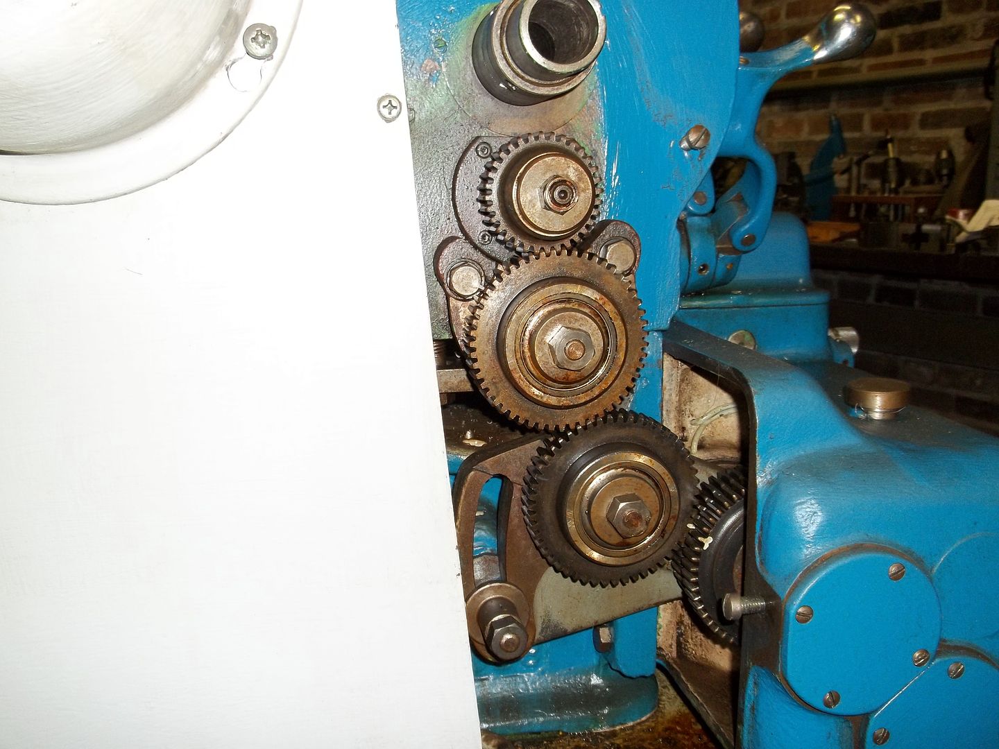
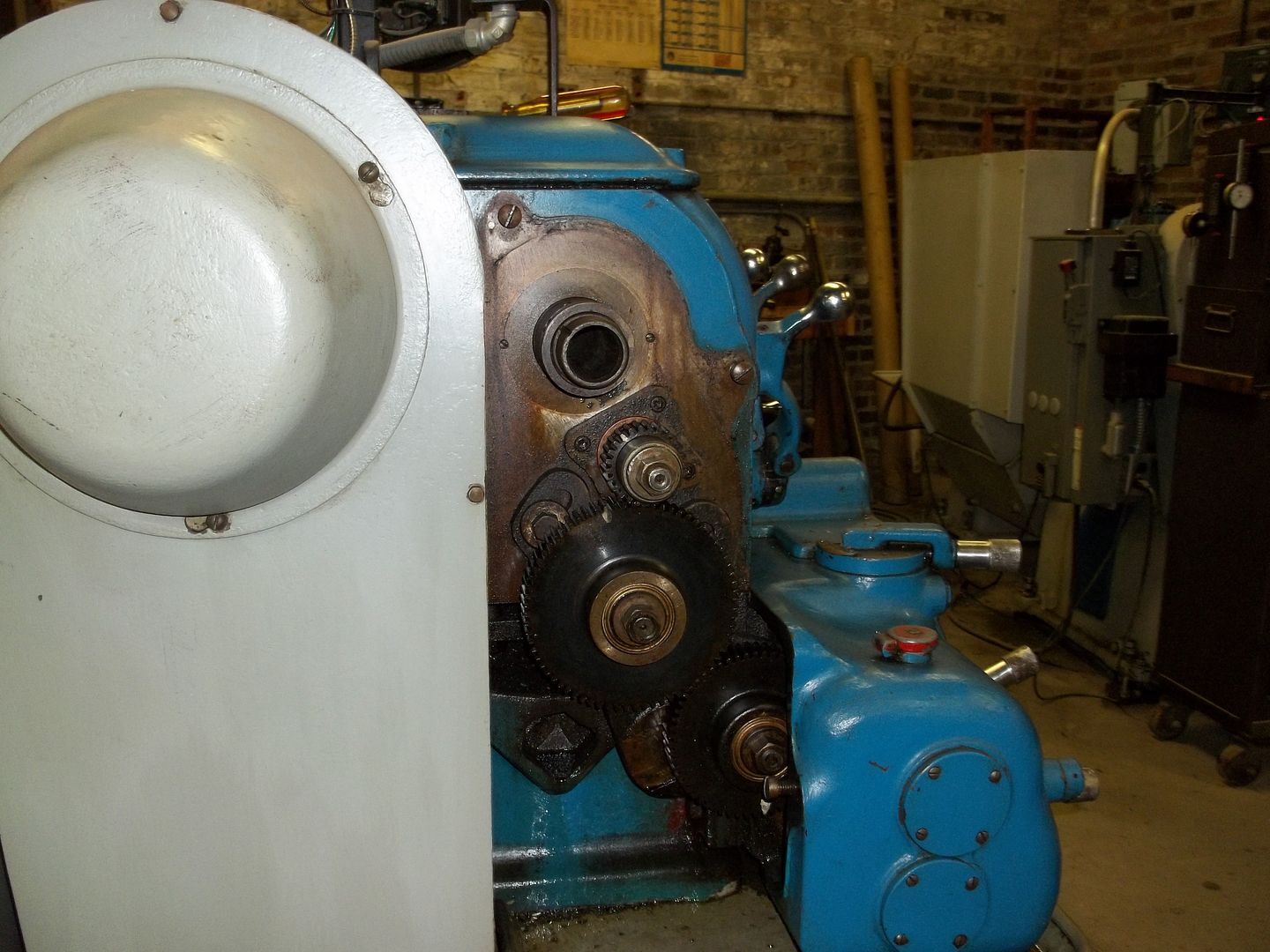
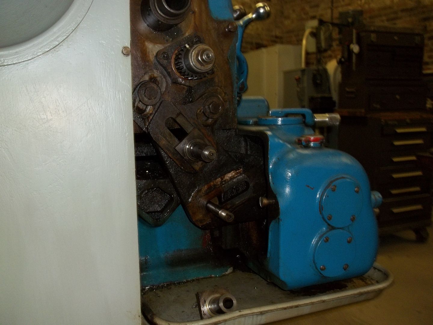
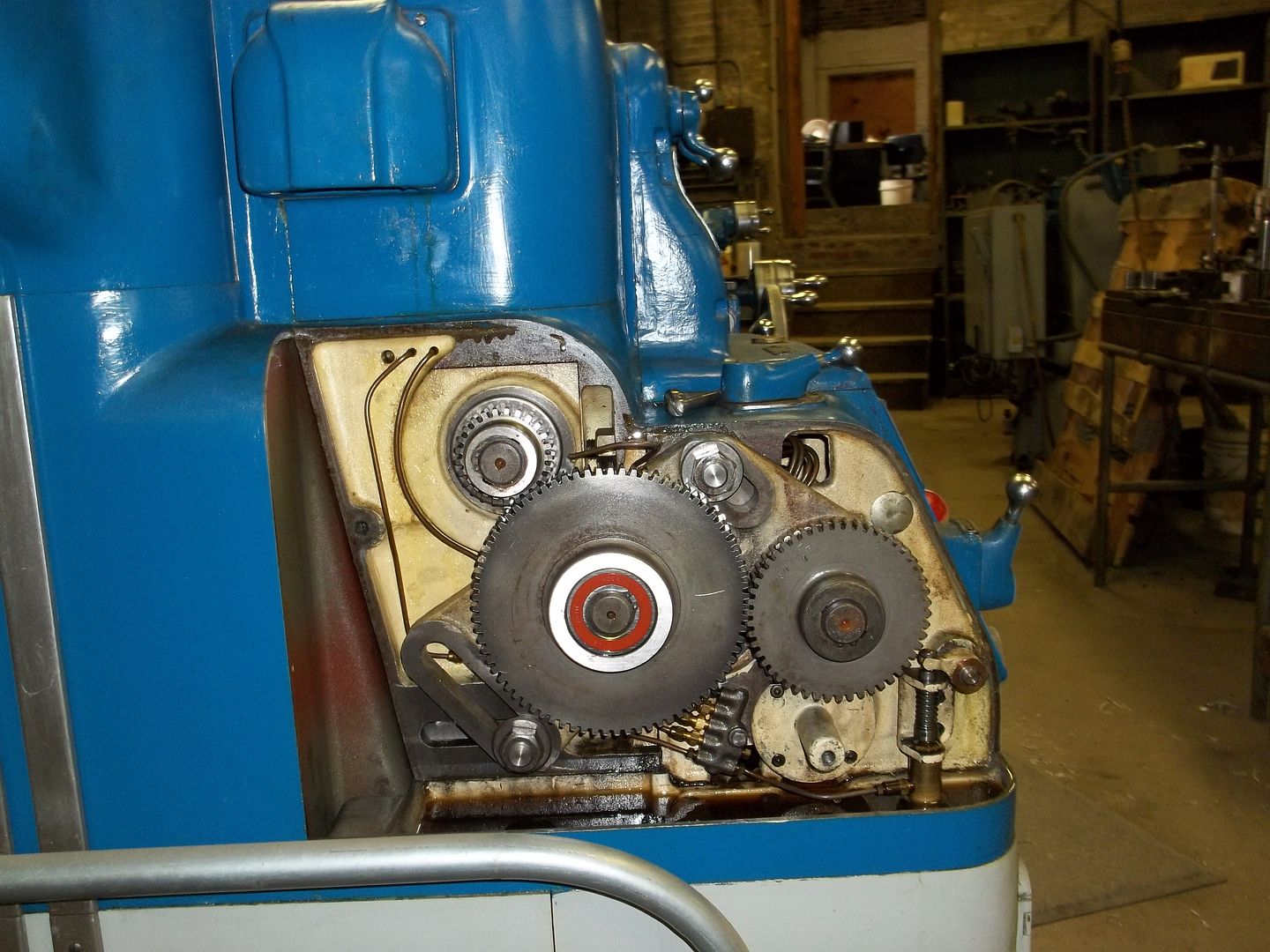
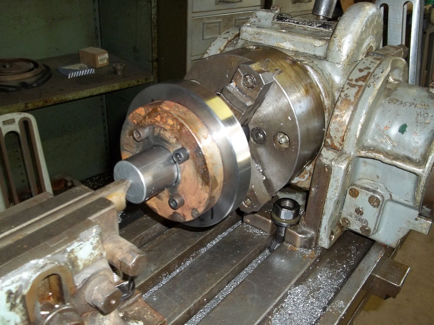
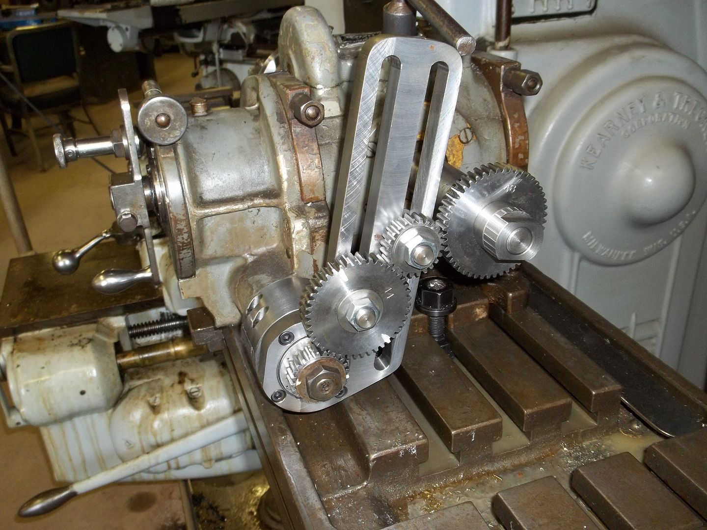
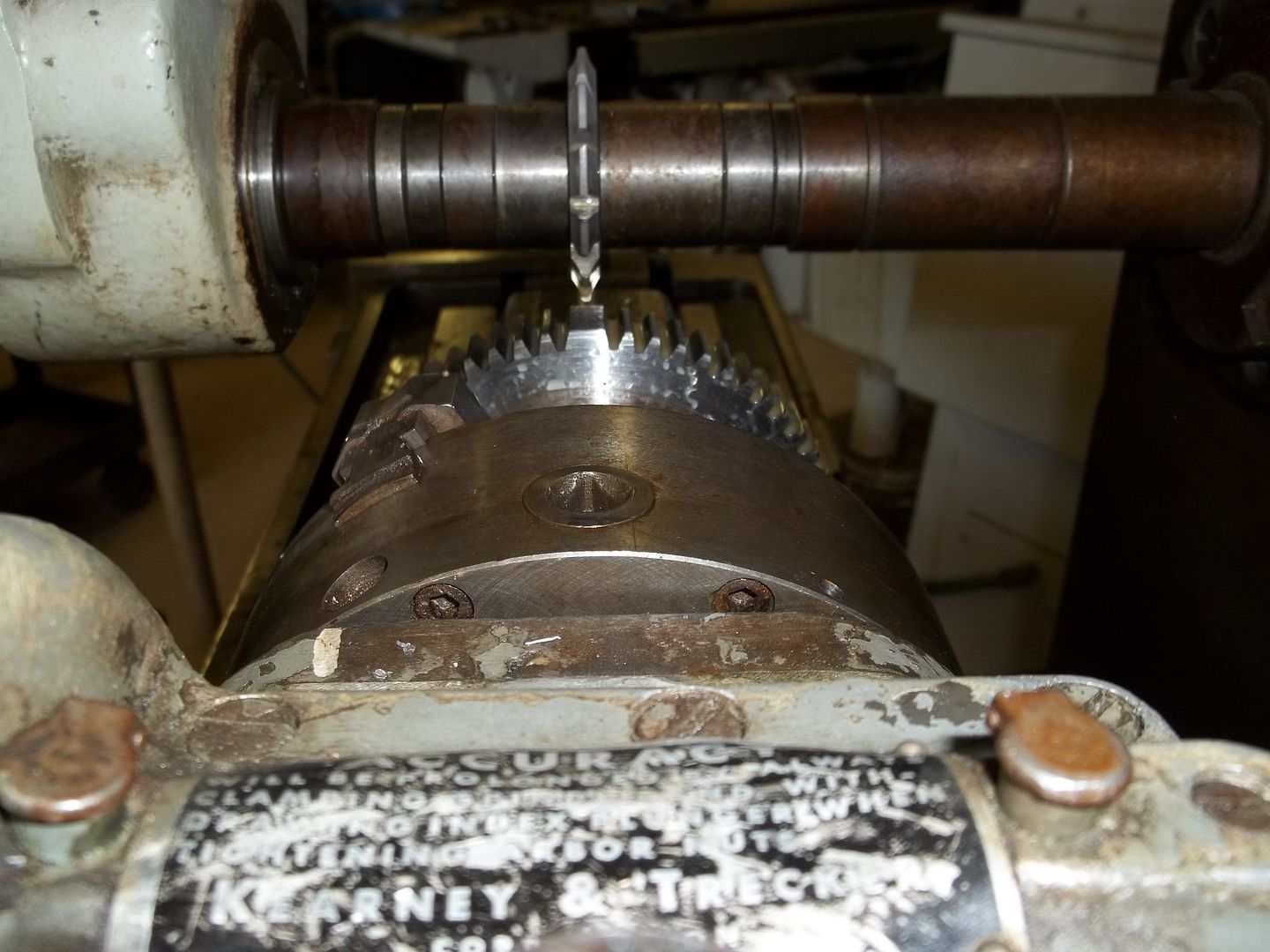
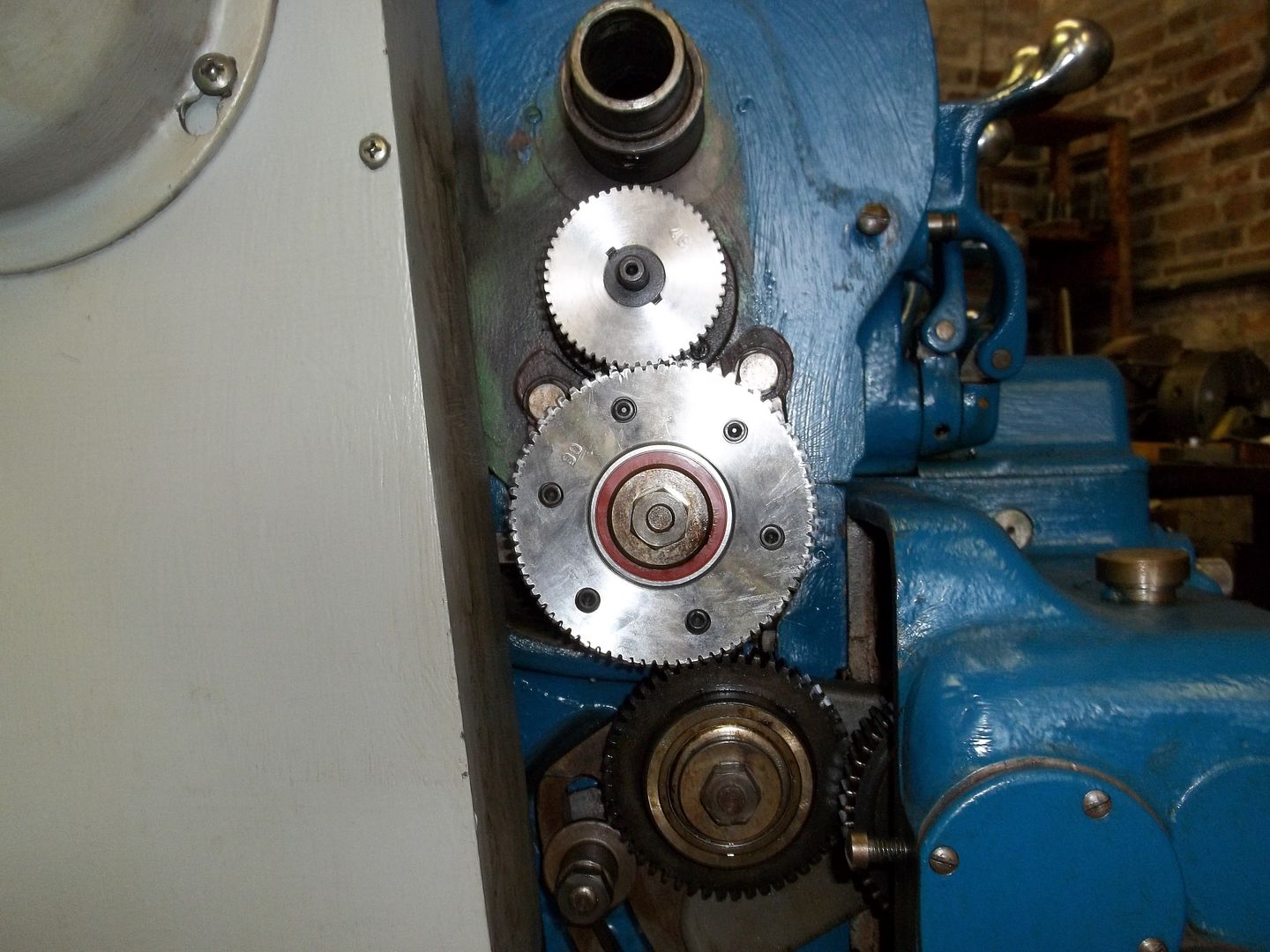
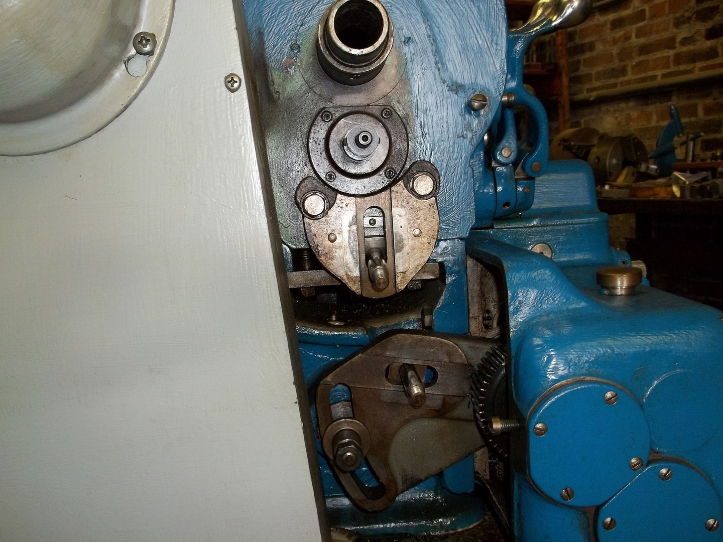
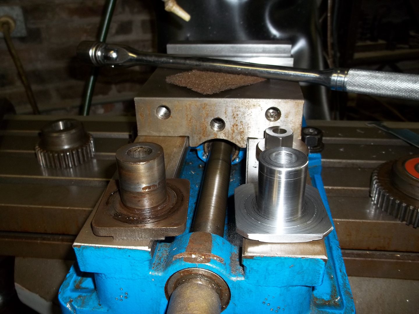
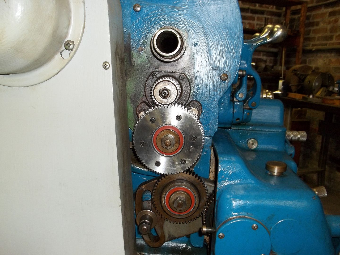
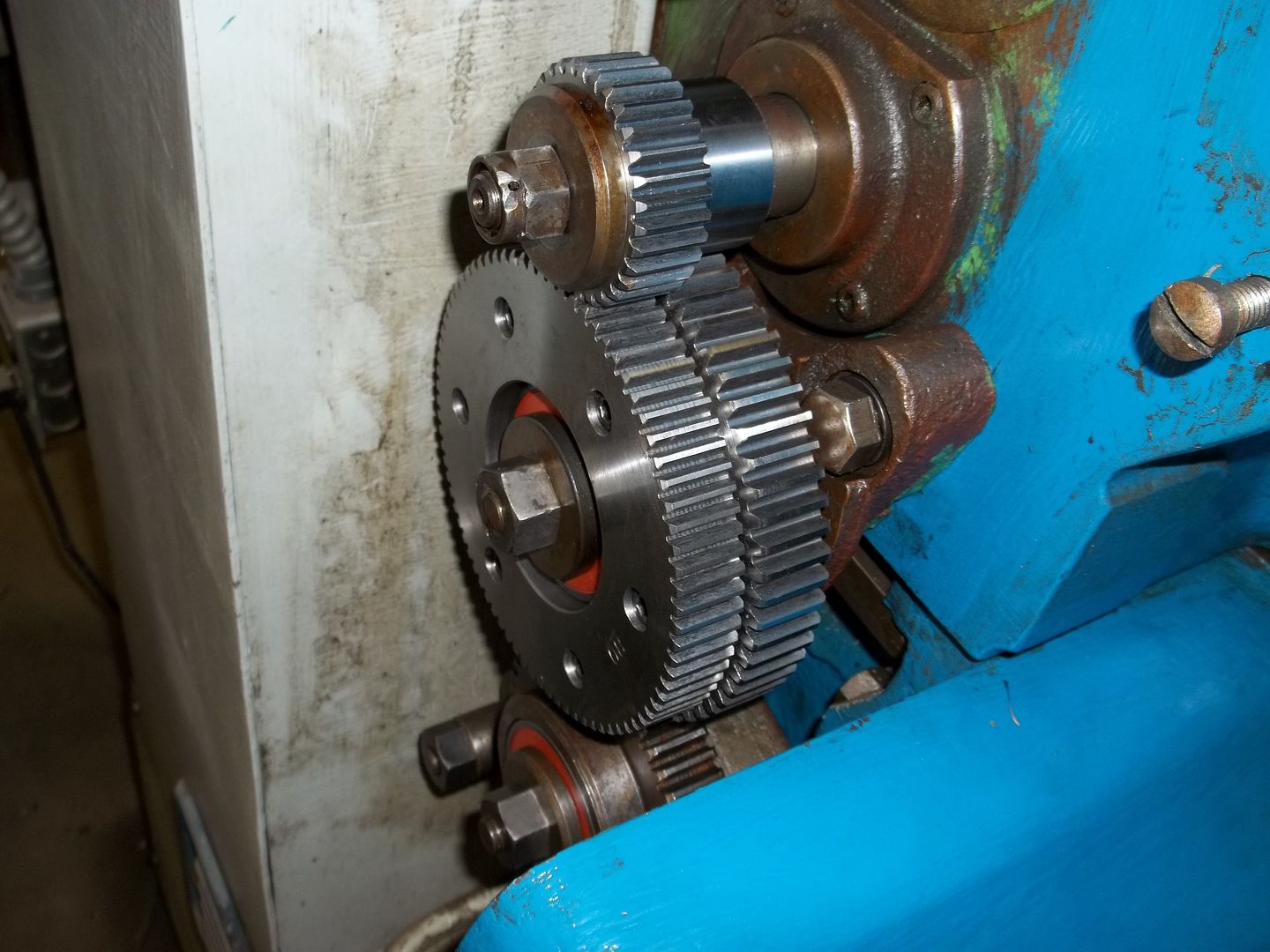
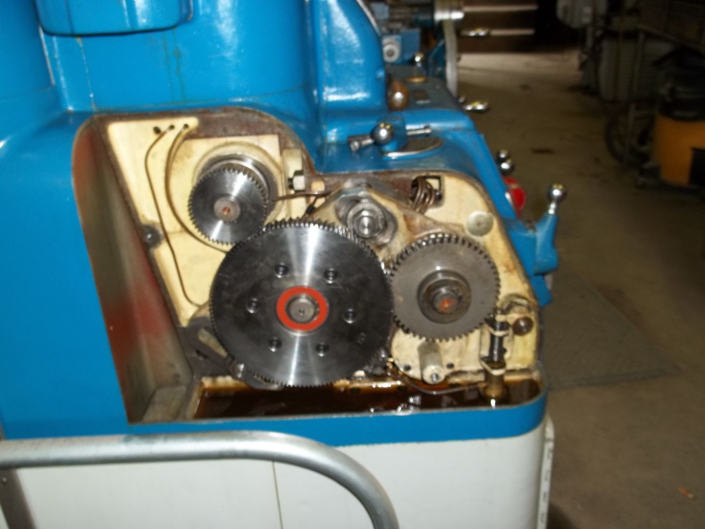
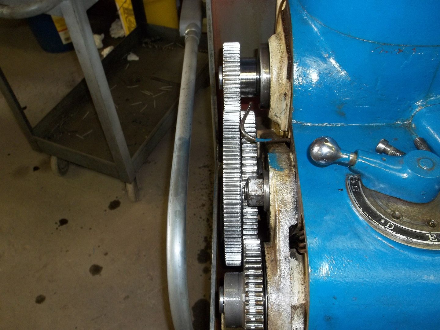
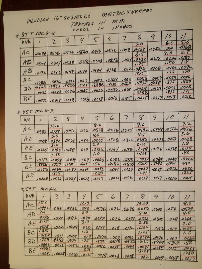
Well, I thought the SE 60 was going to be easier than the CK, but I had a little surprise. It seems that the person, who shall not be named, that last worked on the end gearing 3 years ago Loctited the the bearings to the shaft to keep the inner race from spinning on the shaft. Had to take the entire quadrant assembly off the lathe, and get the gear puller out. It came off, but not easily. Then after getting things cleaned up and the quadrant remounted, went to install the compound gear, but the outer bearing covered up the snap ring groove on the shaft. Needed about 1/8" more. Off comes the compound gear, get the bearing out, removed the outside internal snap ring, got the 1/8" needed, and reinstalled the bearing, then back on the lathe. Other than that, it was easy.
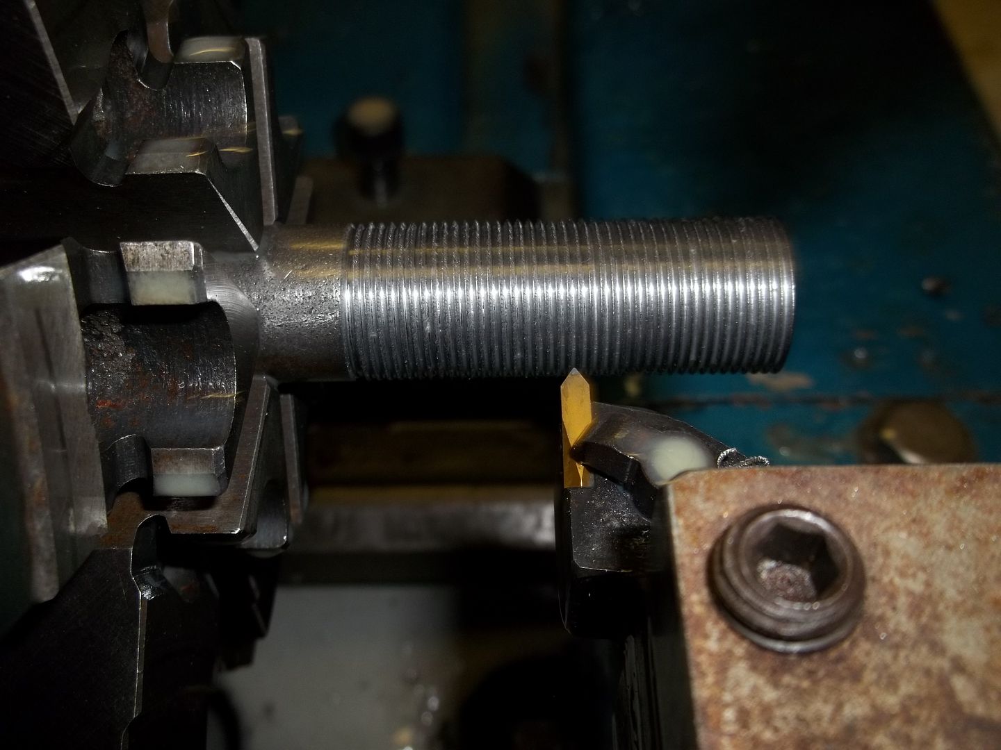
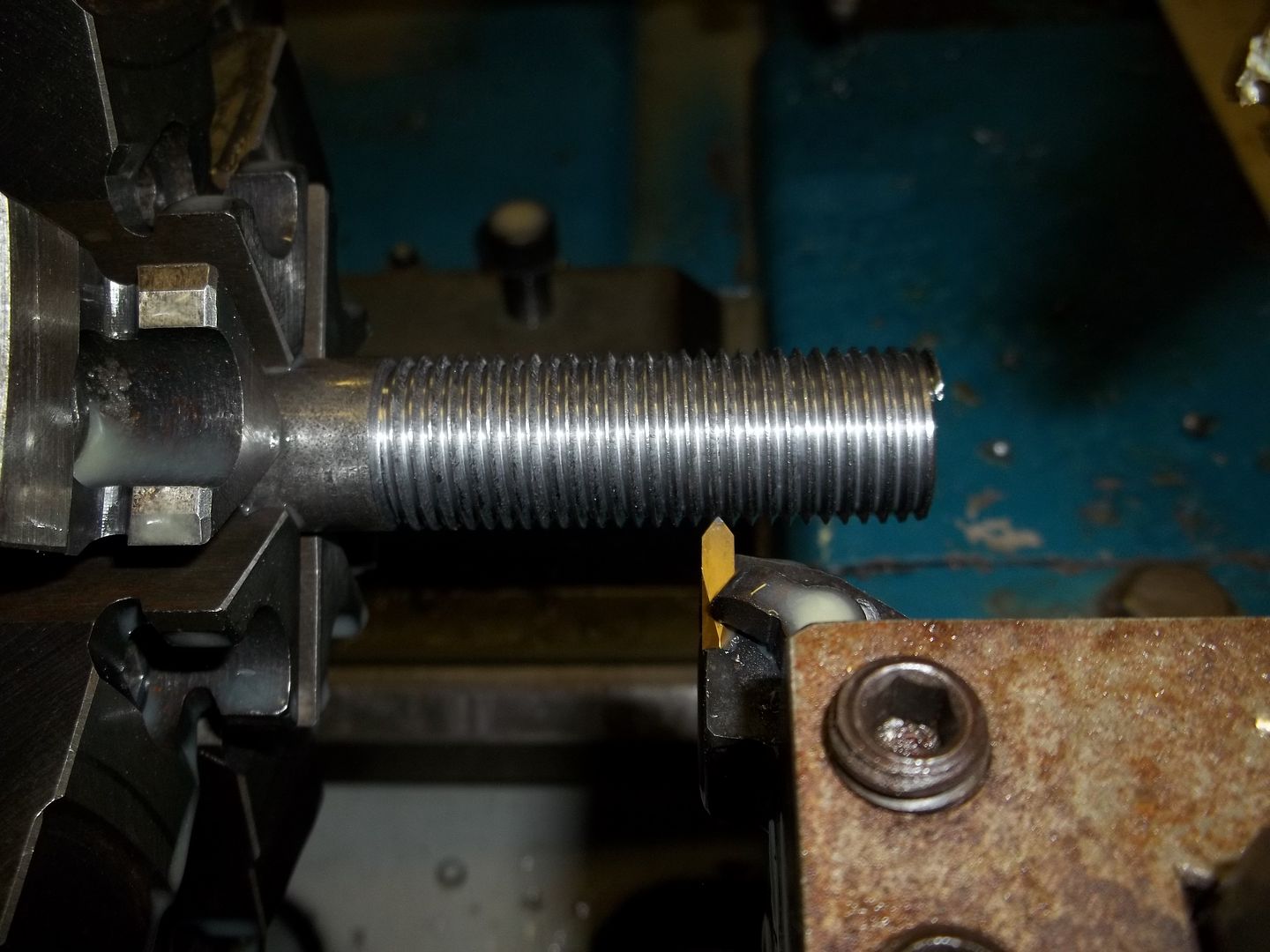
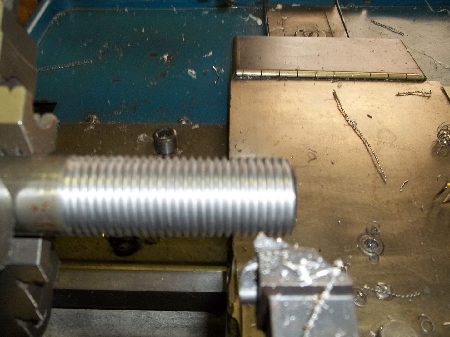
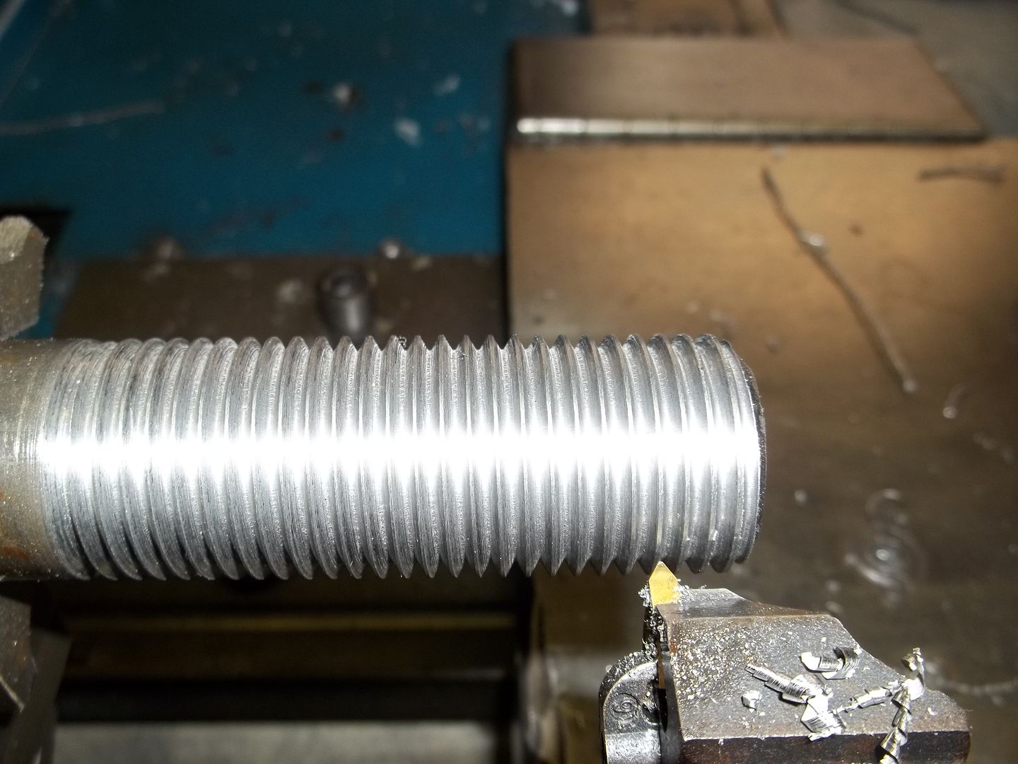
Cut 2 threads using the 50 T MCG, 1.25 and 3 MM on a 1-3/16" 1045 shaft. No coolant was used, and I was pleasantly surprised how well the threads looked. RPM was approx 250, that speed on the speed chart is mangled, so I'm guessing.
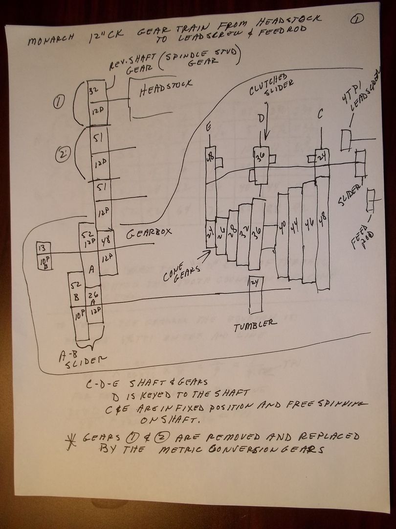
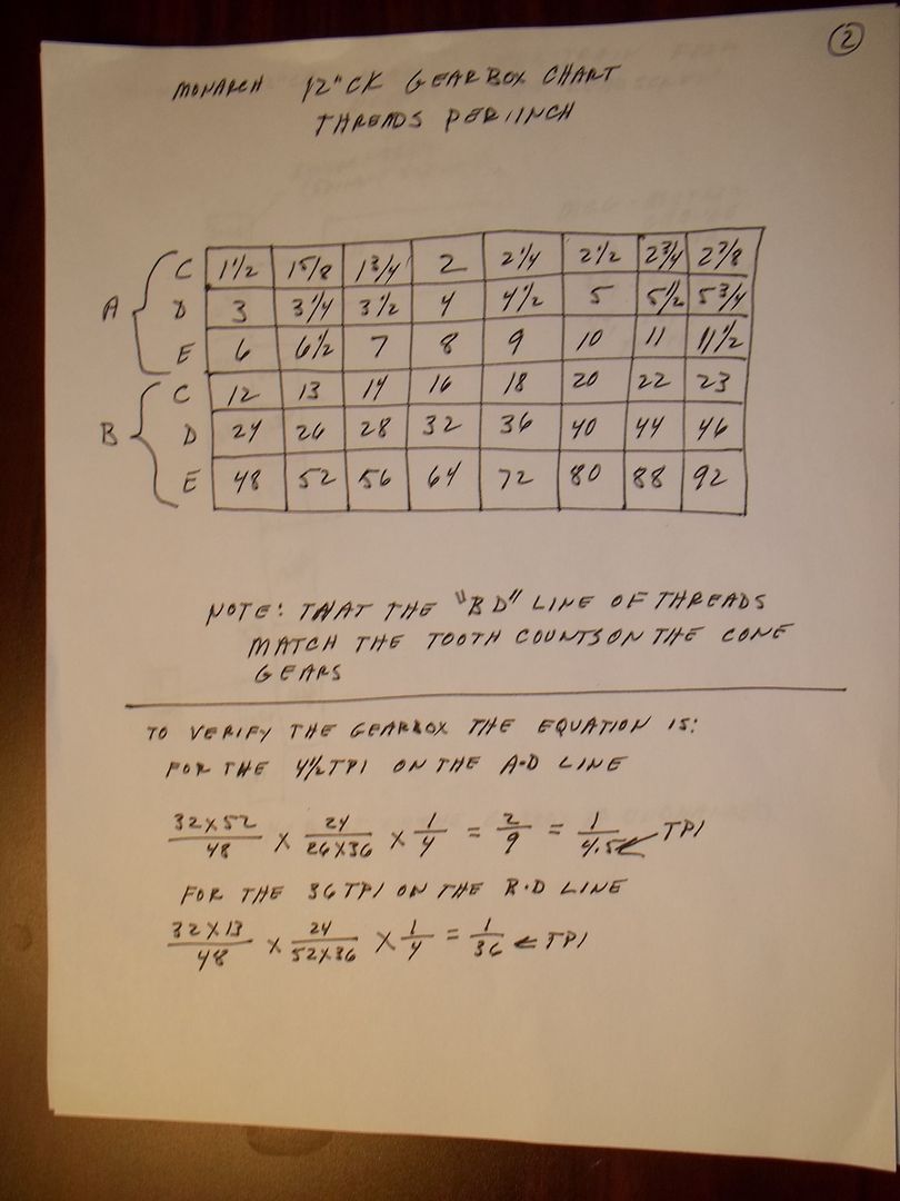
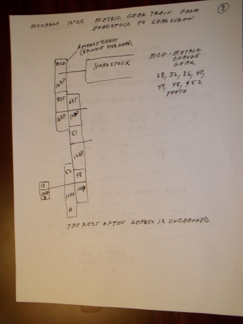
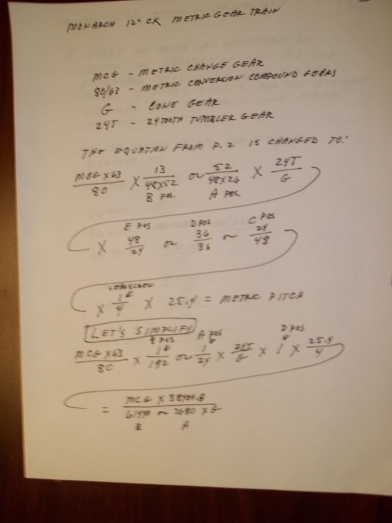
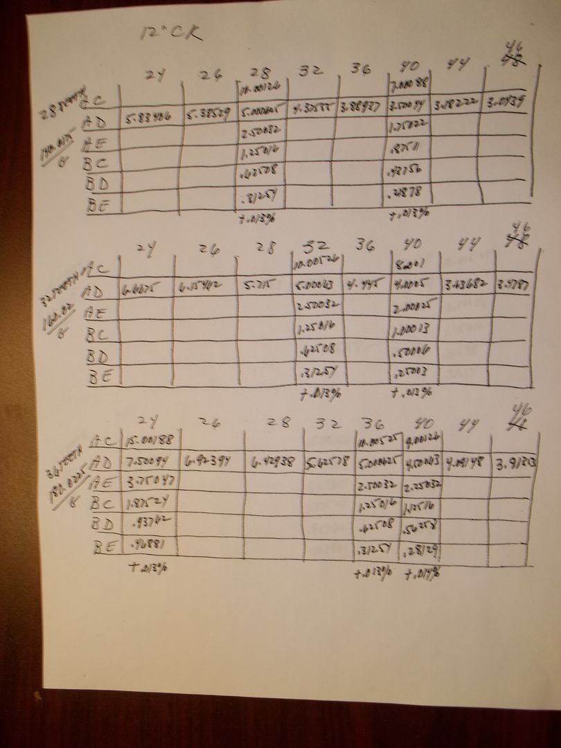
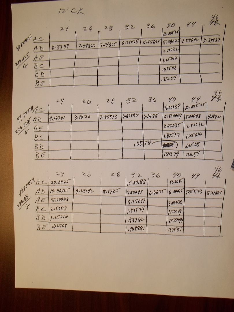
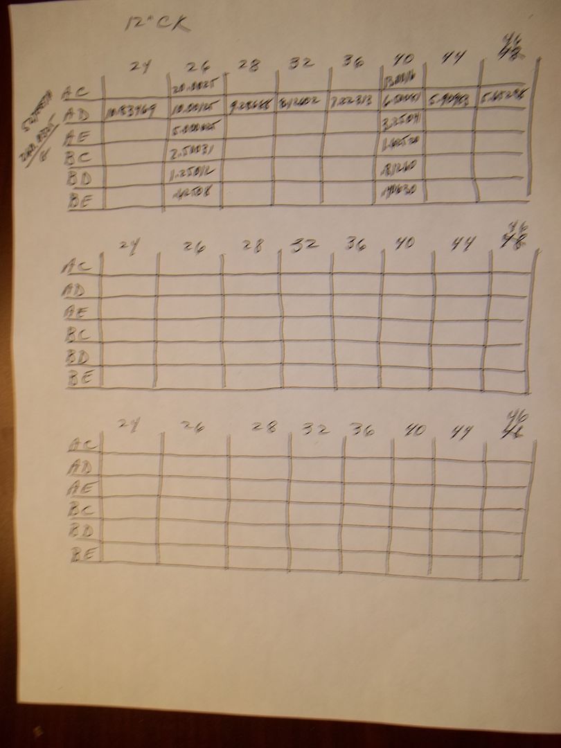
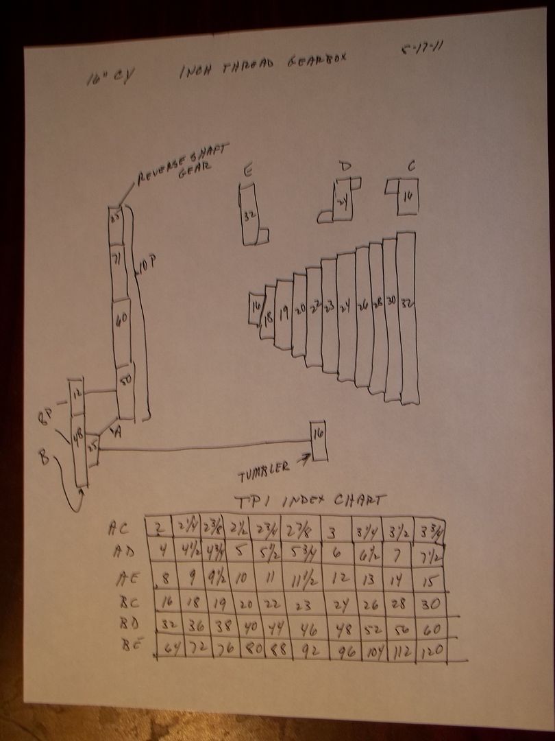
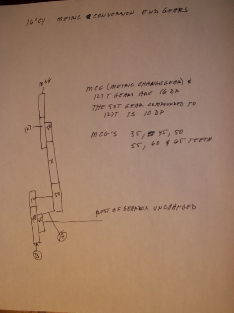
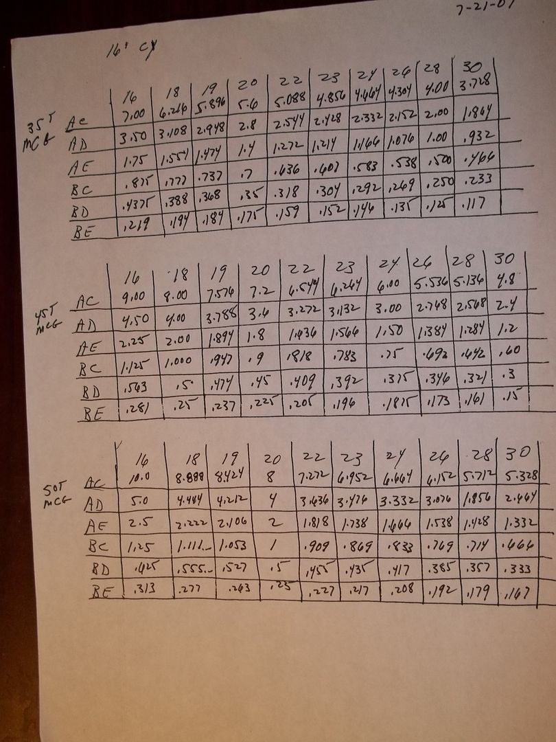
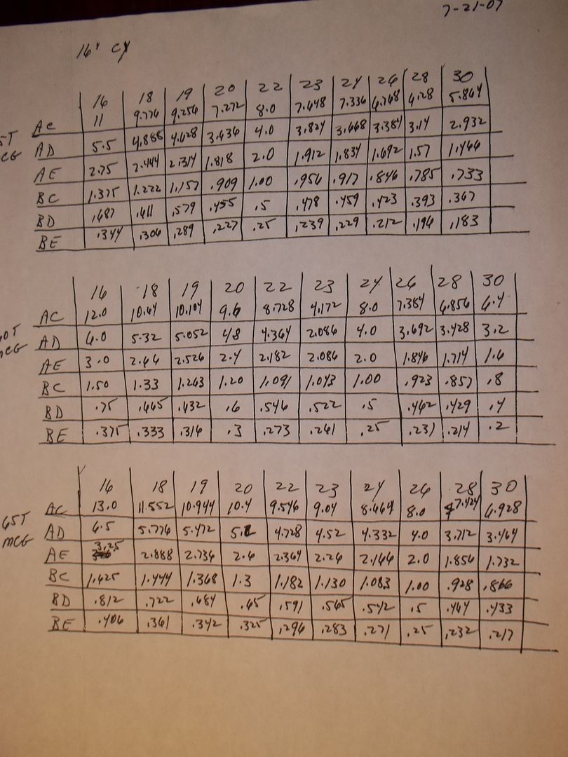
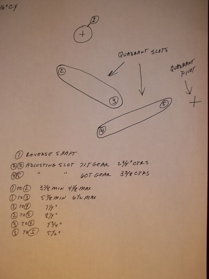
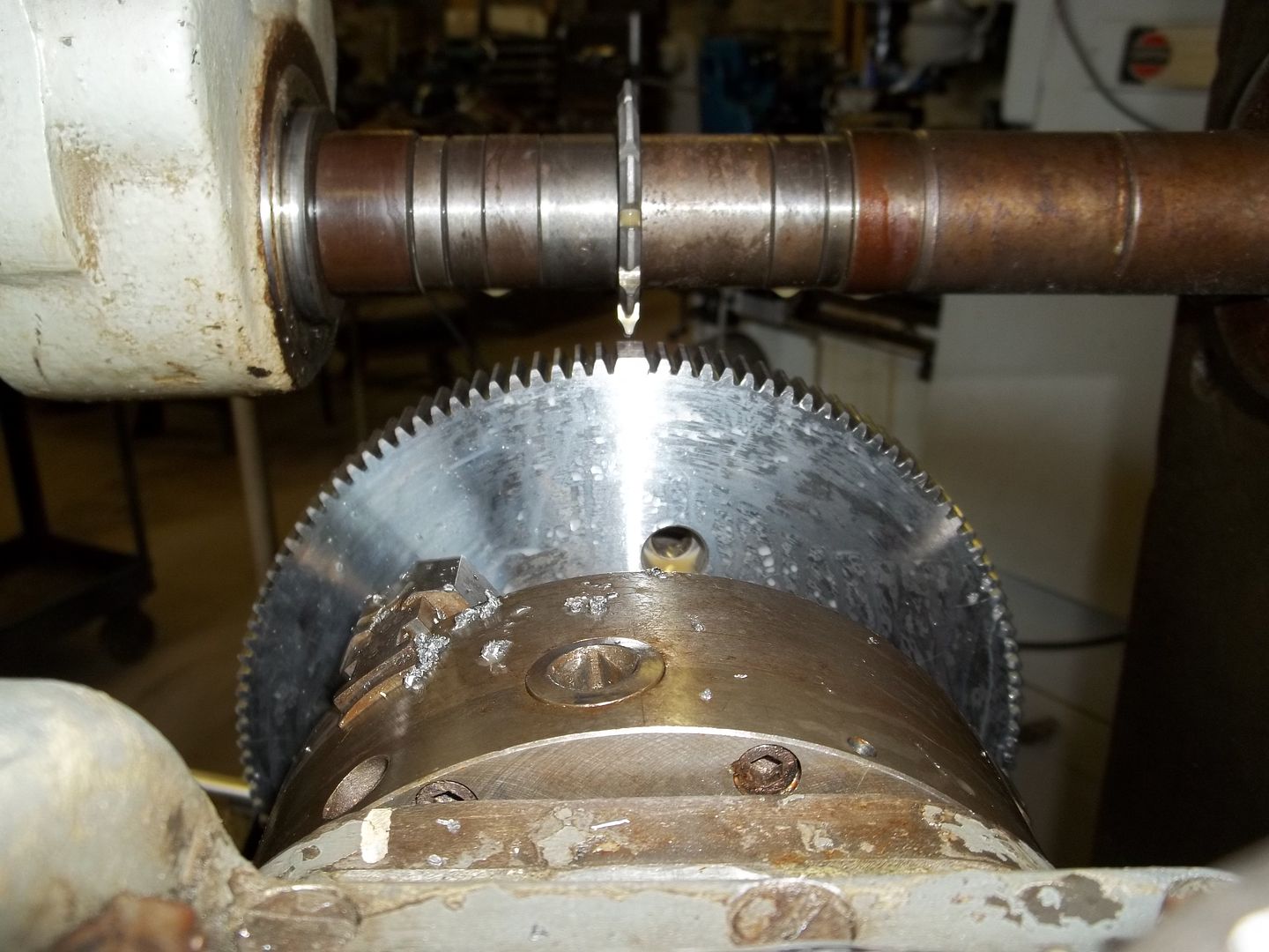
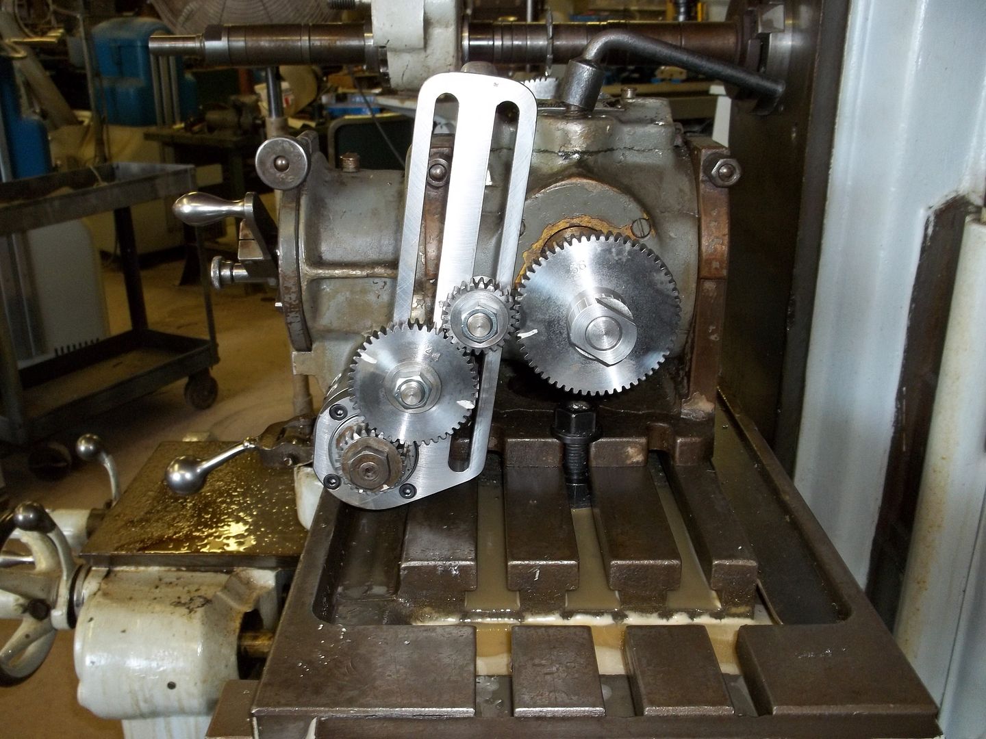
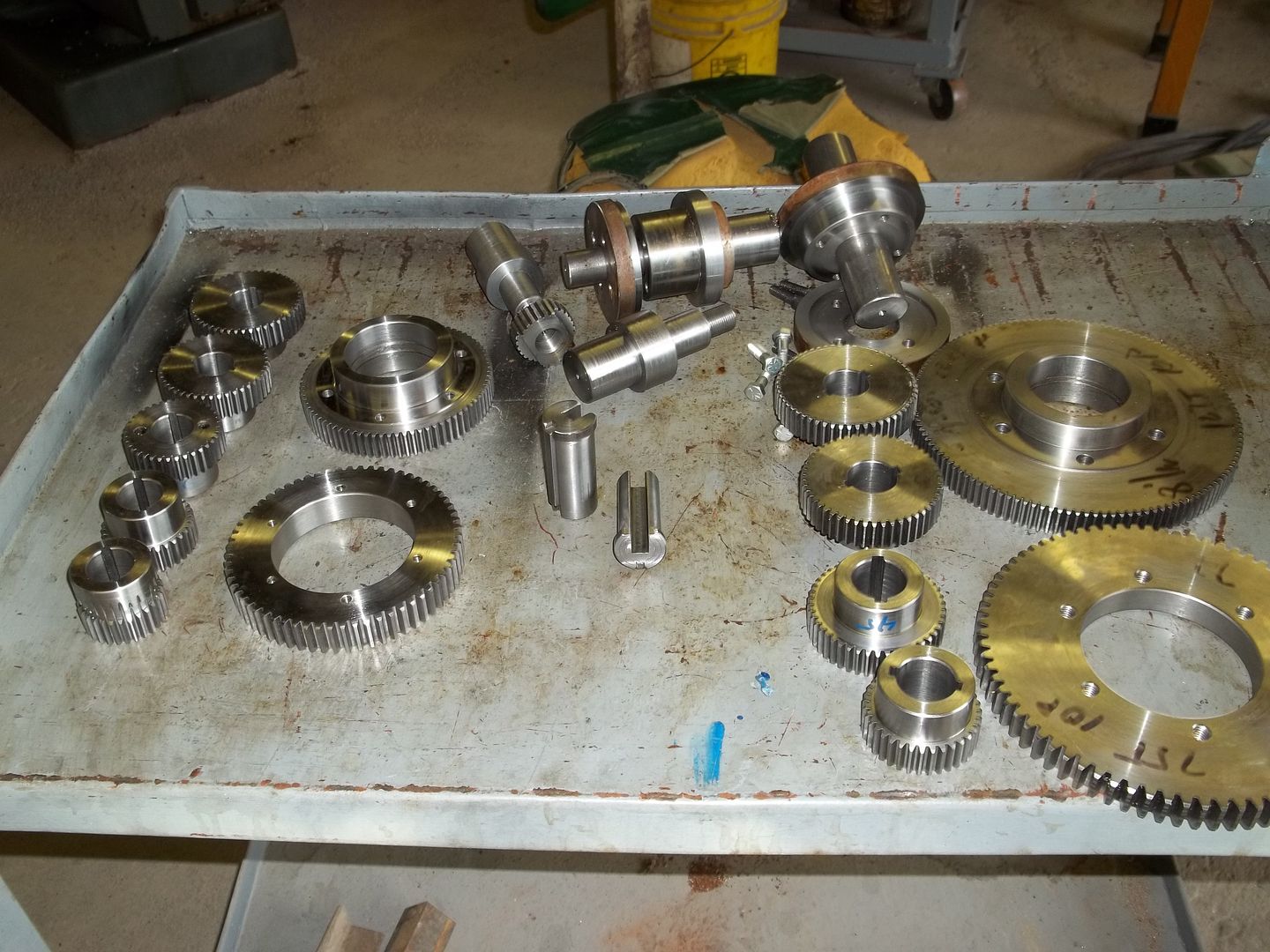
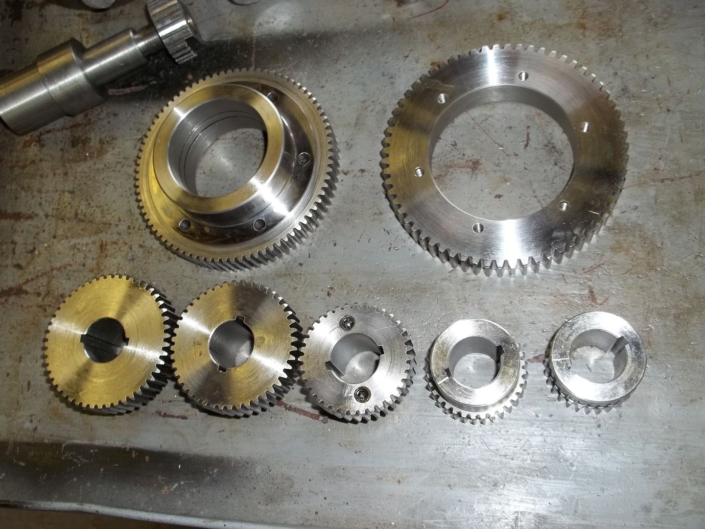
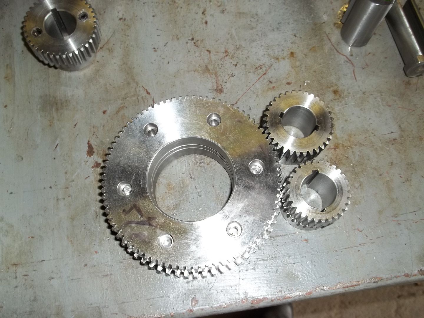
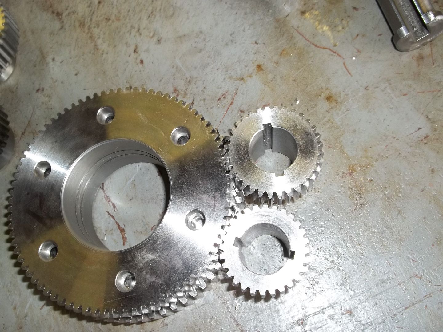
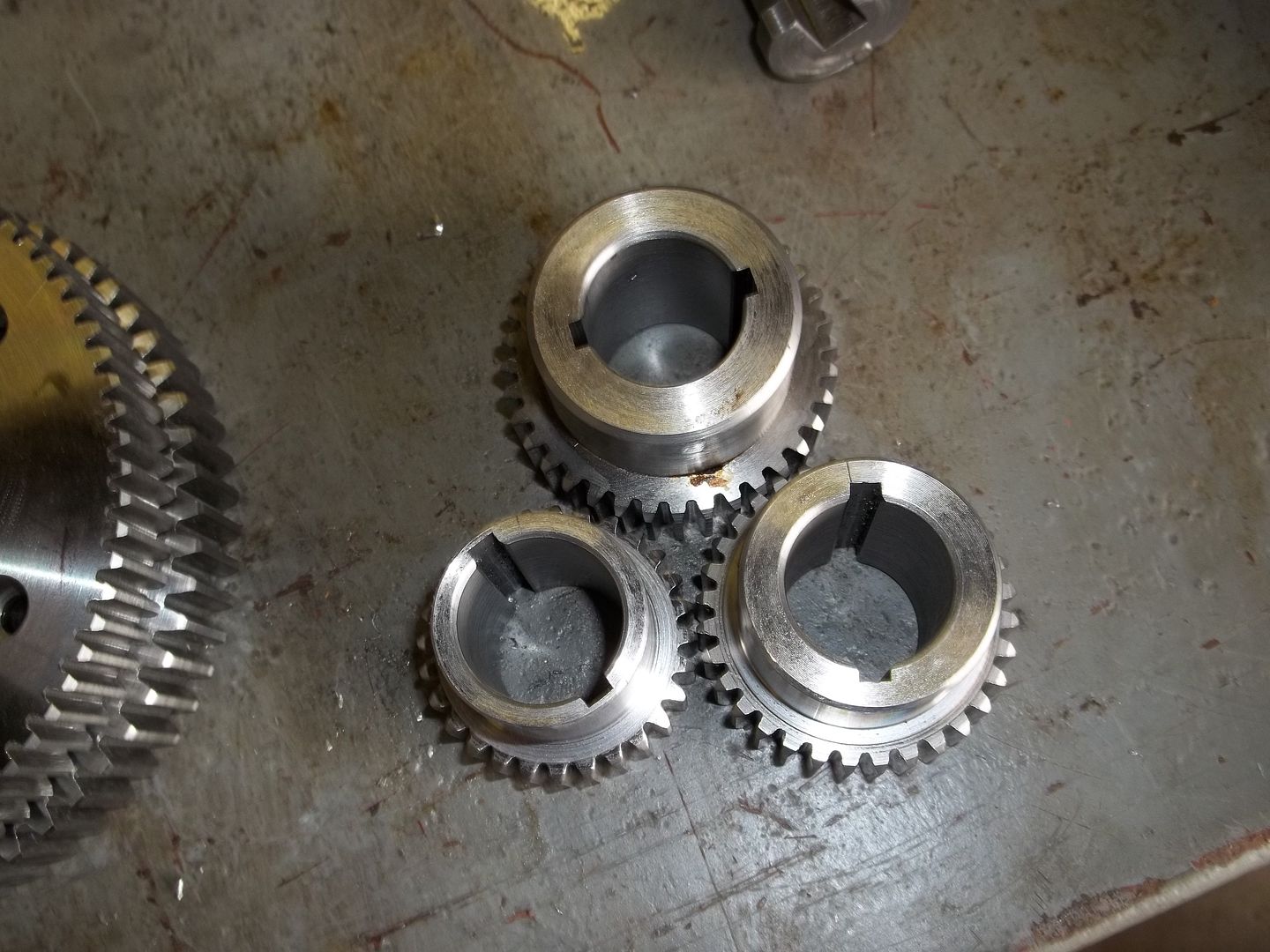
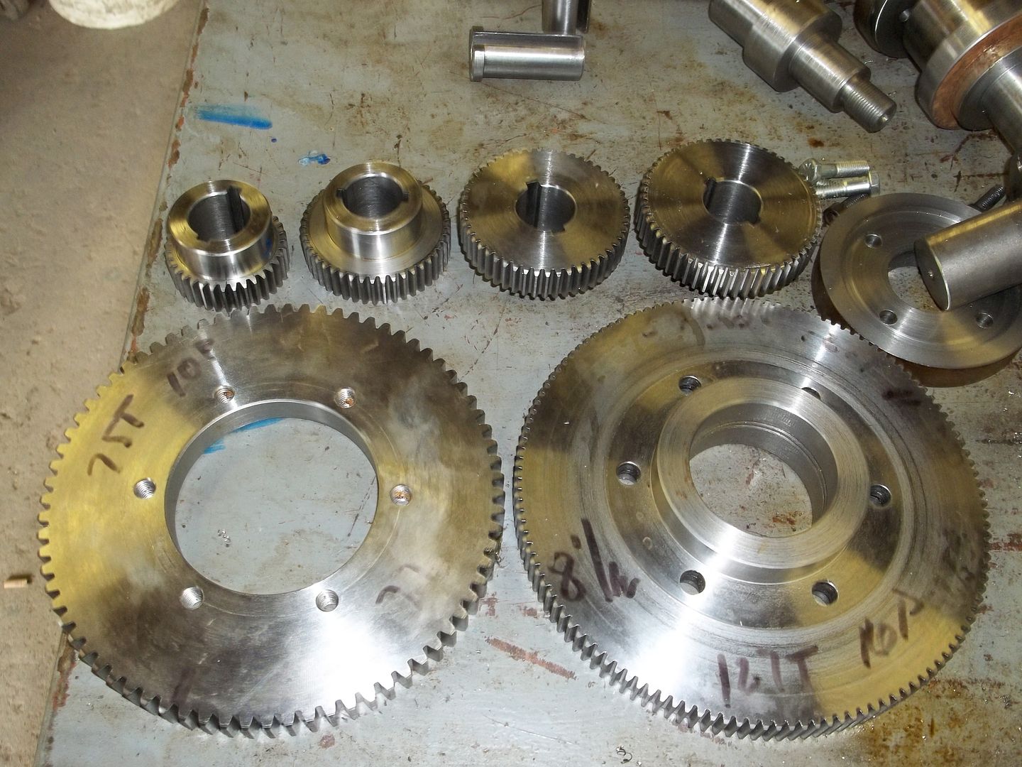
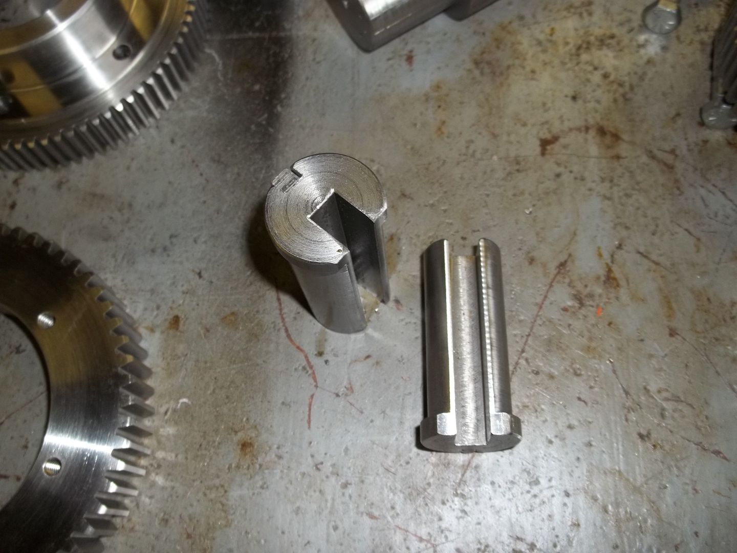
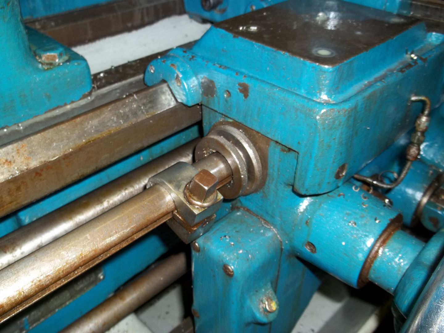
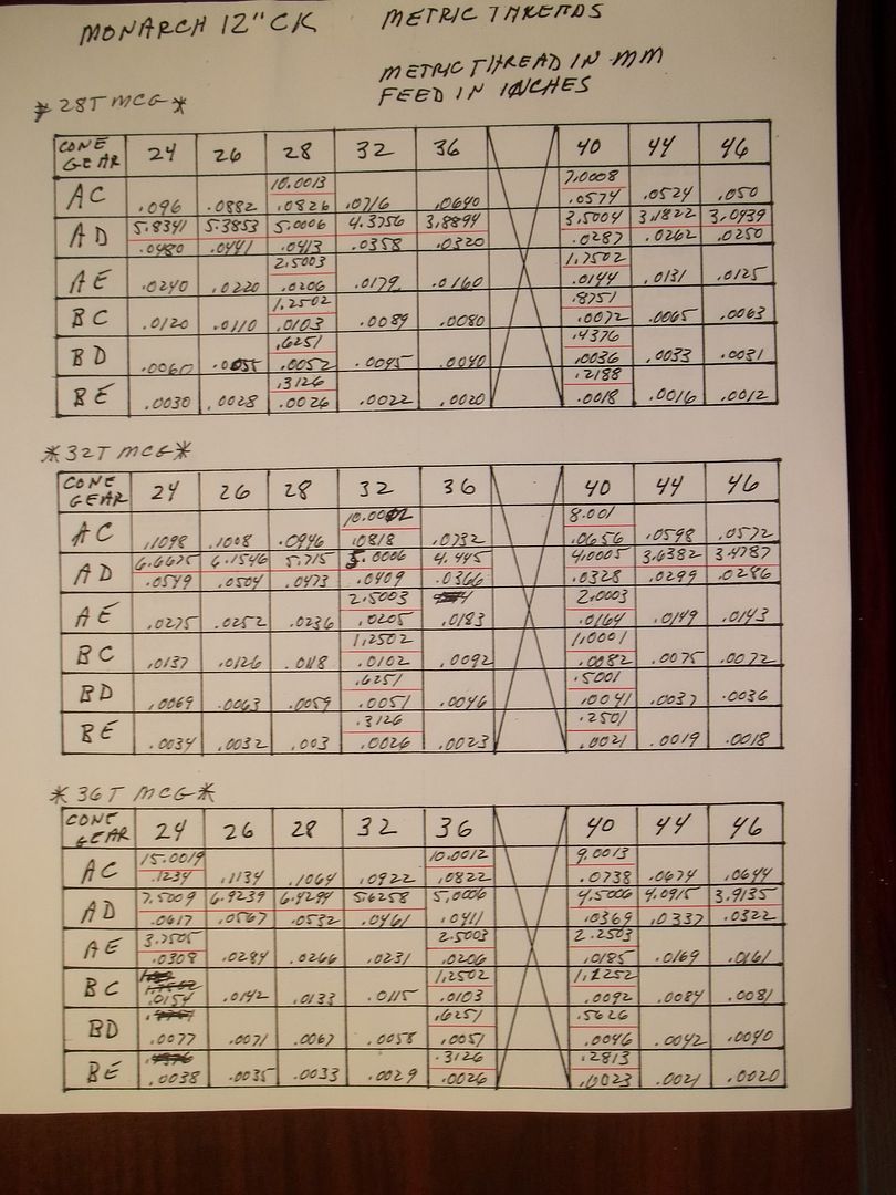
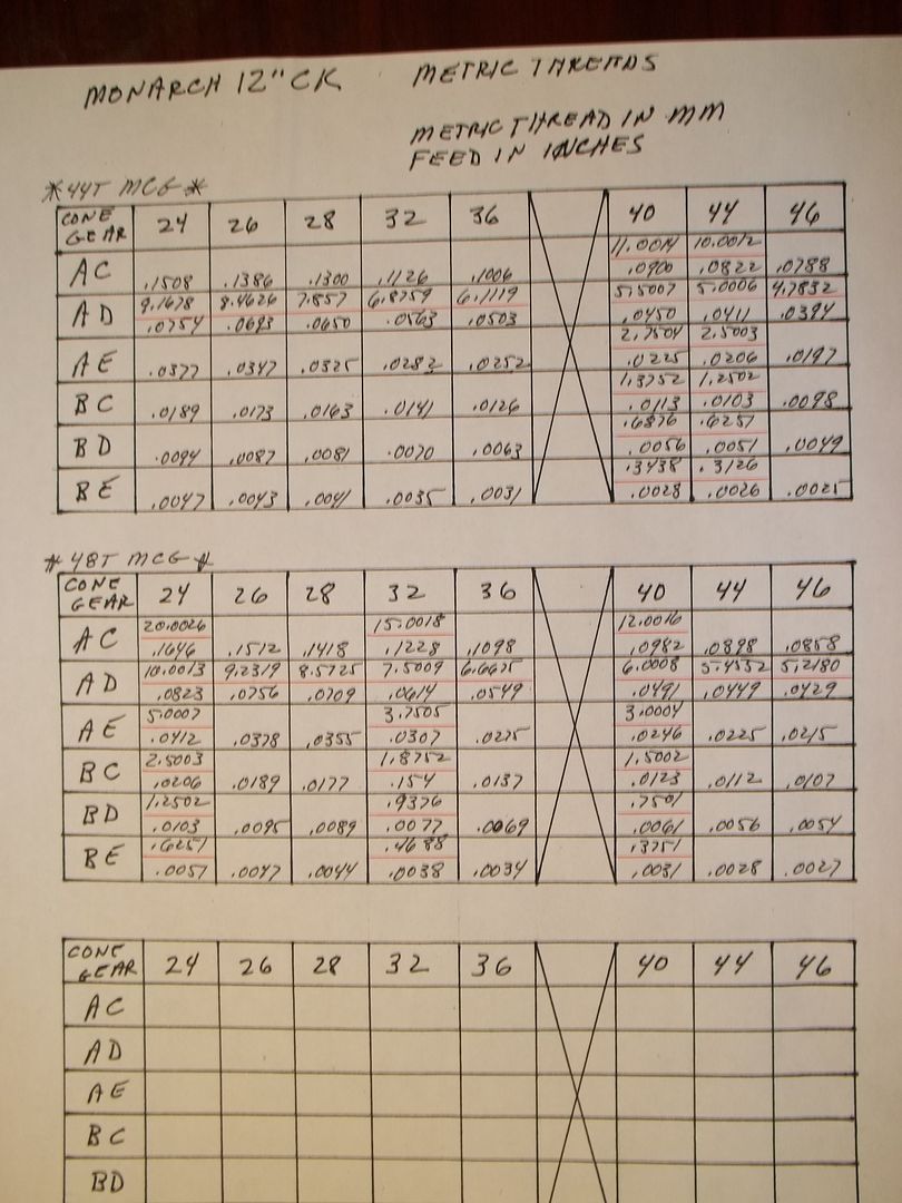
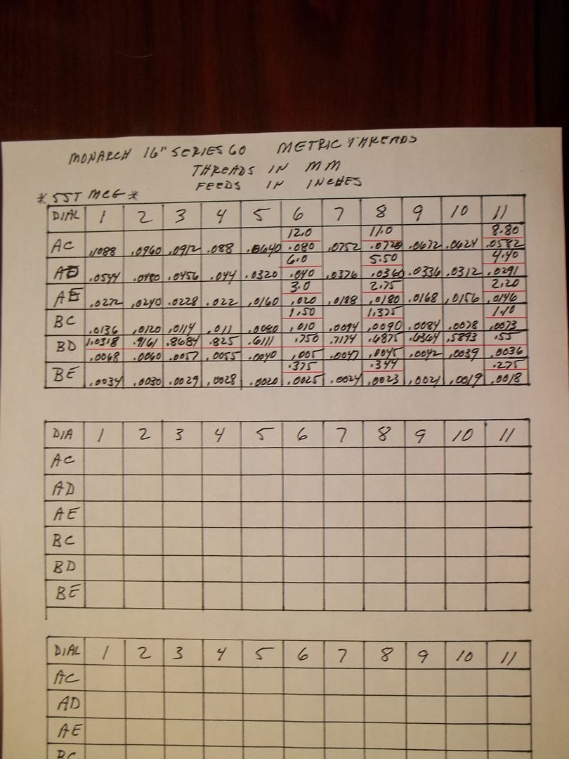
I think the pictures are self explanatory.
100_0121.jpg


100_0122.jpg


100_0124.jpg


100_0125.jpg


I have yet to clean up the charts for the SE 60, but they are very similar to the ones for the CY.
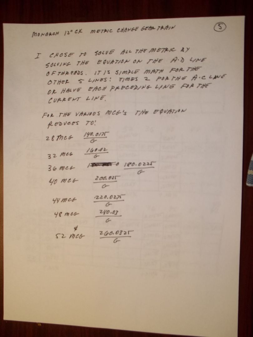
I made spread sheets for all the gears, for the CK and SE 60, mainly to see how many duplications there are, and which gears I didn't truly need. If you look at the charts above, there are quite a few threads that aren't listed in Machinery's Handbook, after listing all the metric threads I could find, and there are quite a few. This included the minature, Lowenhertz, Trapezoidal, and regular. I think my final selections have a comprehensive coverage. I'm not concerned about the "No-See'um" threads, I just have a very hard time envisioning cutting anything under .5 MM on these "big" machines. Conversely, I don't think I'm going to be cutting those 20 MM Trapezoidals either. I'm just looking for the common metric threads.
In a few days I'll post the revised charts, hopefully with the feed rates.

If you're concerned about the accuacy of the threads for the CK, with the 80/63 compound gear, the threads listed are carried out to the 4th decimal place. May not be good enough for a leadscrew, but they are very close.
Harry
 
Here are the thread charts for the CK and SE 60 lathes with the turning feed rates.
The feed rates were established by first figuring the ratio between the inch thread pitches converted into a decimal number and then divided into the feed rate for that pitch. This was done all for every pitch across one line of the chart on the gearbox I used the BD line for the SE 60 and the AD line for the CK. It doesn't make any difference which line, but I had to pick one. The ratio is not constant for the different pitches, but they will hover around one rate. For the SE 60 the ratio varied from .166 to .168, for the CK from .208 to .210.
On the charts you will see that same reference line figured for metric threads for each cone gear. The metric pitch was converted into inches, and multiplied by the ratio to get the feed rate in inches.

100_0138.jpg


100_0140.jpg


100_0141.jpg


100_0143.jpg


I have apparently included a metric pitch selection, 15MM with in the column, which isn't listed in MHB, at least I didn't have it listed on my list. Looked like a good number, oh well.
Not all of the underlined pitches are good, either, they just had the misfortune of being in the same column as the good pitches. The reference lines are totally underlined, either multply by 2 or .5, for some "useless" pitches.
Harry
 
Am I missing something? I have been cutting metric thread on my Monarch, Sidney, American, and Hendey lathes for years without the need of any special gears except one. A 125 tooth gear to match the pitch of the gear train. Just about all the gear companies sell 125 tooth gears. Computing the ratios a few change gears along with quick change selections can cut all metric threads. 125 is the smallest number 25.4 can divide evenly into. All the lathes I used had the feed reversible feature like the Hendey has so that it was not necessary to reverse the spindle to restart the cut since the thread clock will not work. Frank


Back
Top