10k
Plastic
- Joined
- Nov 14, 2012
- Location
- Houston, Texas, USA
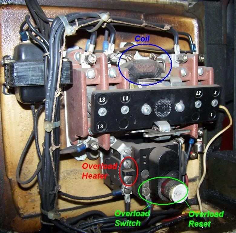
I recently acquired a 1943 Monarch 10EE. At some point, someone replaced the original contactor and heater. Unfortunately, the new contactor is at least an inch taller than the original, and the cover plate won't fit on top of it. To remedy this, he had placed some 1/2" shims between the cover and the lathe. Additionally, although the new heater has a reset button, it is not the correct size/shape and location to fit into the reset hole in the cover.
When I first took the cover off, I found swarf in with the contactor. This concerns me. Swarf and 220V don't mix.
I want to replace the contactor, at minimum, and possibly the heater. I looked around on this forum, and the original contactor seems to have been a Cutler Hammer 9586. I looked on eBay, and this seems to encompass older, open type contactors and more modern contactors.
Does anyone have the right part numbers for the contactor and heater, or could someone recommend a more modern contactor and heater that will fit in the housing?
Thanks in advance for any help. If someone has these left over from a VFD refurb that they'd like to sell, I'd be interested.


.jpg")
