What's new
What's new

Monarch 16CY Clutch Pulley Removal Help

Typical171

Plastic
Joined
Dec 11, 2016
Hello,

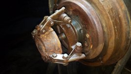
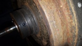
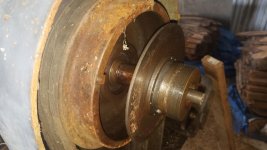
I recently purchased a 1942 16CY. I need to remove the headstock to lighten up the overall weight so I can pick the lathe with my skid steer, so I want to remove the belt pulley guard and to do that it looks like I need to get the clutch pulley assembly off. I'm going to refurb this lathe so I need to remove the headstock anyway. I looked through the forum and found some good info but it seems my clutch is slightly different then the ones I seen posted. Anyway here is a pic of mine. My question is I never had one of these apart and just need to know what and where are any set screws I need to loosen and basically how to remove this assembly. Thanks for the help.
Joe
attachment.php
 

Attachments

  • 20180920_120910.jpg
    20180920_120910.jpg
    88 KB · Views: 159
yeah, that is an option but it has to come apart anyway and I have 4800 lb lift capacity with the Cat
 
I will be going through this on my 1941 CW myself this weekend, and will let you know the steps - I think the clutches are identical. From my examination it looks like the outer spider will come off with a 3-jaw puller, then the clutch disc, then the pulley which is mounted on two bearings with a spacer.

That's the plan, will report how it goes.

Hey I would appreciate that, good luck!
 
WON"T WORK... Now for Plan "B"

... From my examination it looks like the outer spider will come off with a 3-jaw puller, then the clutch disc, then the pulley which is mounted on two bearings with a spacer...

Well I started down this route and luckily didn't get very far! I removed the outer nut, hooked up the 3-jaw puller and applied some heat. When nothing was budging and I was afraid to apply any more pressure I decided to break out the clutch diagram. I feel like an idiot because it's obvious now that the outer spider (Monarch calls this the Sliding Sleeve) is threaded. You can see the threads if you look in the gap between the Sliding Sleeve and the Adjusting Yoke.

The clutch adjustment instructions say to "withdraw the adjustment lock pin"...doesn't really say HOW to withdraw the pin, that's for us to figure out. (I circled this in the photo.) Then screw the yoke in or out to adjust.

So Plan B calls for me to mark which hole the lock pin is in and then depth mike the projection of the threaded Brake Rod to the surface of the Sliding Sleeve, so I can come back to the same setting. At that point I think the assembly will unscrew completely, exposing the friction discs and pressure plates, and give access to the pulley bearings.

I hope this helps if you now get ahead of me in your disassembly of the clutch.
 

Attachments

  • 20180817_160920b.jpg
    20180817_160920b.jpg
    99.1 KB · Views: 112
Well I decided for now just to get the headstock off was to leave the clutch alone and just unbolt the belt guard and rotate it up that gave me the clearance needed to pick the headstock and carefully lay it down on a pallet while I pick the rest of the lathe. The 289D work like a champ and I was able to remove the lathe from the goose neck trailer and safely locate it for storage. ( Im in the process of building my shop and just needed to get it off the trailer)
I did run across something I was not expecting to see. The lathe came from a GM metal fabricating plant and when I picked the headstock I noticed a few thin shims under the chuck end and on the V ways. I keep them to later measure what they are but when I went to clean the two mating surfaces to set the headstock back on the bed I could feel a ridge like area, low spot near where the shims were on the headstock. Very strange, almost like it was worn but I would think that would be impossible since these are static surfaces, didn't make sense to me. I will have to investigate further on what I was seeing there.
 
So Plan B calls for me to mark which hole the lock pin is in and then depth mike the projection of the threaded Brake Rod to the surface of the Sliding Sleeve, so I can come back to the same setting. At that point I think the assembly will unscrew completely, exposing the friction discs and pressure plates, and give access to the pulley bearings.

I hope this helps if you now get ahead of me in your disassembly of the clutch.


Yes this does help thank you
 
Clutch Disassembly Pt 1

Began disassembly, refer to the pics below. The Lock Pin is spring loaded. I grabbed it with pliers but it would probably have pulled out with finger pressure alone. As you unscrew the Sliding Sleeve the Adjusting Yoke unscrews with it on a separate thread. The gap between the two widens, but you'll have to hold the Lock Pin out as you rotate because it keeps wanting to fall into the adjustment holes. After a few turns the Lock Pin doesn't reach the holes anymore.

The outer pressure plate slips right off, which is as far as I got. the photos are in the order I followed. Apologies for the fuzzy pic of the caliper, my measurement was .776"
 

Attachments

  • 20180925_072548.jpg
    20180925_072548.jpg
    98.4 KB · Views: 159
  • 20180925_072625.jpg
    20180925_072625.jpg
    94 KB · Views: 109
  • 20180925_072757.jpg
    20180925_072757.jpg
    97.6 KB · Views: 157
  • 20180925_072939.jpg
    20180925_072939.jpg
    99.1 KB · Views: 124
Thank you for taking the time to document this it helps a lot. From the way it looks at this point, the threaded hub looks to be set screwed onto the shaft? Its looks like the one I have and definitely a slightly different design from the ones I can find on the net.
 
Clutch Removal - Pt 2

Looks like my last post was vaporized, so here it is again...

Got the Friction Disc off (finally). It pilots on its OD, against the ID of the sheave, so the fit is close like everything Monarch. You have to pull it STRAIGHT off or it will bind. I resorted to LIGHTLY screwing two drywall screws into opposing rivets (just until they bit) which gave me something to grab. You must clean ALL the crud from the exposed ID of the sheave or the disc will bind. It weighs about 5 lb, so you have to lift slightly as you pull or it will bind. Did I mention that if you look at it crooked it will bind?

Once out, the rear pressure plate/integral hub is held in by a setscrew 90 degrees from the keyway. Once again, no way to grab it. My puller jaws won't fit in the gap between the OD of the disc and the ID of the sheave. I threaded the Sliding Sleeve Assembly back on until the big thread engaged, then tried the puller on the cast body of the rear section. The outer threaded shaft just compresses in because that's what the lathe's clutch lever does, ie pulls the rod in to engage the clutch. It looks like if I cut a spacer out of 3/4" copper pipe and slip it over the outer threaded shaft, it will prevent the clutch rod from pulling in by bearing on the keyed shaft. The puller should then be able to pull the rear pressure plate off the shaft, exposing the sheave bearings. Sorry this sounds confusing unless you're looking at the parts. When I give it a try I'll try to get a good photo of the setup.
 

Attachments

  • 20180926_074333.jpg
    20180926_074333.jpg
    93.9 KB · Views: 104
  • 20180926_074221.jpg
    20180926_074221.jpg
    96.9 KB · Views: 107
  • 20180926_074203.jpg
    20180926_074203.jpg
    87.7 KB · Views: 93
  • 20180926_074152.jpg
    20180926_074152.jpg
    92.1 KB · Views: 107
  • 20180926_074114.jpg
    20180926_074114.jpg
    98.8 KB · Views: 122
Clutch Removal - Final

It's finally off safely... Had to think on it some because the rear pressure plate just wasn't pulling off. Seemed like too much force even with the setscrews loosened.

That's because Monarch put another secret setscrew underneath the first! (See photos). I remember a reference to this being done in a location inside the headstock.

So, there are two sets of setscrews at 90 degrees apart. The upper is a hollow screw used just for "jam-nutting" the lower dog-point setscrew. There are counterbores in the shaft so they register in place and don't mar the shaft. Once all these setscrews are removed the pressure plate slips off pretty easily. The upper sheave also pulls off easily. I just used a screwdriver on each side levering against the cast iron shroud.
 

Attachments

  • 20181008_103336.jpg
    20181008_103336.jpg
    93.7 KB · Views: 107
  • 20181008_104005.jpg
    20181008_104005.jpg
    93.8 KB · Views: 102
  • 20181008_104321.jpg
    20181008_104321.jpg
    95.7 KB · Views: 103
  • 20181009_074603.jpg
    20181009_074603.jpg
    92.2 KB · Views: 102
  • 20181009_074621.jpg
    20181009_074621.jpg
    77.3 KB · Views: 86
Last edited:
Good to see the progress, and its always a plus to get something disassembled without damaging components. Where are you taking this disassembly? Is it a cleanup and reinstall to get the clutch working or going further then that.
 
This is a complete restore job. See this thread for what I am starting with:

https://www.practicalmachinist.com/vb/monarch-lathes/16-monarch-lathe-near-richmond-va-150-a-352711/

It's much better than it looks, just will take lots of cleanup. Will have to replace all the Taper Attachment bearings and the crossfeed screw thrust bearings, plus some handwheel knobs.

Just got the quote back from Monarch on the thrust bearings - $45 each! I think not... I will be engineering a replacement with 12mm thrust bearings (readily available and greater load capacity) and a bushing for the ID, which is more like $4.50 each.... gotta save $$ for the tooling I don't have!

**UPDATE**
Excuse me, I miscalculated. The quote is confusing. The bearings from Monarch are $45.20 each, but that's just the BEARING... balls in a cage. It shows $45.20 for Qty 2 but says "each". The thrust discs are $135 each, and there are four of those. So the total cost is $180.20 or $630.40 depending on how you do the math.
 
Last edited:


Back
Top