What's new
What's new

monarch 60 series ideas

idacal

Hot Rolled
Joined
Aug 9, 2011
Location
new plymouth id
I have my lathe i think its a 60 series its a good lathe but the wear up by the headstock is starting to effect my work. its still quiet in the head stock. or maybe im wanting to work to better tolerances without using feet of emery cloth. I have a ridge for a bout 40" of the ways then it kicks up right by the chuck. my lead screw in this section doesn't look to good either. my options are. I have been thinking about getting a smaller lathe for finishing, don't really have the funds or space right now, send this one off to get it reground dont think that's an option, would still need a lead screw, and other stuff, and its a 132 between centers. I would still have an old lathe thats has 700 rpm for top speed, shorten the lathe, remount the head stock, and then clean up the cross slide? most of that would just be time. its not a commercial enterprise but I need it to work when I need it. or look at stepping up to a newer poreba or toolmex type lathe. I like the length of this one but I 99% of the time im working in the first 12"
 
Ya, Ide have to agree with phil here. You got a big burly machine for hogging off material. If You do 99% of your work in the first 12" and precision is what you need, maybe you should look for a 10EE. Ide at least use it as an excuse if you're married. Youde be surprised how little space a 10EE really takes up. I use my big lathe at work the same way. Get my stuff close to where I want it and then finish it up at home with a 10EE. Don
 
I have some thoughts, be curious some opinions. Look at Harry's Another New Toy thread, approximately page 9:
Another New Toy

Shorter bed than op here, but he faced a similar problem. His solution was to use tail stock base as a sled. He built a jig that would attempt to plane the ways. And a chain and sprocket assembly to pull everything during planing.

He noted a few problems. One, the chain and sprocket was not smoothe enough in operation, so apparently it left indication marks during planing. Another was a flame hardened bed is difficult to scrape. He had some success, but it became difficult to plane.

Having read other older threads, the consensus seems to be that scraping flame hardened beds is damn close to near impossible.

My thought is, why not make a jig similar to what Harry did, but dont plane. Grind. Use a grinder on the jig. And instead of chain and sprocket, use a wire cable hoist to pull.

If you could sort out a fine enough feed, and a way to dress the wheel. . . Tail stock base and TS ways as the reference, it'd be a bit of a project, but potentially doable.
 
Last edited:
I have some thoughts, be curious some opinions. Look at Harry's Another New Toy thread, approximately page 9:
Another New Toy

Shorter bed than op here, but he faced a similar problem. His solution was to use tail stock base as a sled. He built a jig that would attempt to plane the ways. And a chain and sprocket assembly to pull everything during planing.

He noted a few problems. One, the chain and sprocket was not smoothe enough in operation, so apparently it left indication marks during planing. Another was a flame hardened bed is difficult to scrape. He had some success, but it became difficult to plane.

Having read other older threads, the consensus seems to be that scraping flame hardened beds is damn close to near impossible.

My thought is, why not make a jig similar to what Harry did, but dont plane. Grind. Use a grinder on the jig. And instead of chain and sprocket, use a wire cable hoist to pull.

If you could sort out a fine enough feed, and a way to dress the wheel. . . Tail stock base and TS ways as the reference, it'd be a bit of a project, but potentially doable.

I've thought about this some, sled plus grinder.

Harry thought that getting the geometry was a big part of the challenge, so the other thing I think may be interesting to add to the mix is a reference straight edge and a couple of dial indicators. Lets say you bolted a true straight edge in place of the bed rack, not necessarily exactly parallel to the ways but close enough not to go out of indicator range. Then make a sled with three indicators, one on the true straight edge. Run two more indicators, one on any one front way and anther one on any back way. If you tabulate all three indicators as you go down the bed length, you'd get a good idea of bed geometry. Even if the true straight edge is off parallel by .010 over the length of the bed, you know at 1/2 the length of the bed it is off by .005", etc.

Now, if you can use that same sled to hold the grinder, you know how much to grind off along each line you've ran an indicator. I've even thought about adding a indicator before and after the grinder to see if you could determine how much the grinder was taking off in a pass. This might allow you to compensate for wheel wear? Could you couple that with a stepper motor and controller that had the geometry needed? ...
 
i just read thru that thread that was posted I dont think I have the stick-with-itness or the mental ability to do that. plus I would screw up the last step. my lathe works great getting it close and for hydraulic cylinder work and longer stuff. i will start thinking about were to put a 40-48" lathe
 
Thermite your your a character! most of the time it’s just spacers and pins and the average stuff that needs fixed but I got the lathe for the times I’m dealing with hydraulics my local shops are weeks out, and when they finally get to it then they are waiting on supply’s so the 2 times a year I need the length more than pay for the space used
 
Harry thought that getting the geometry was a big part of the challenge, so the other thing I think may be interesting to add to the mix is a reference straight edge and a couple of dial indicators. Lets say you bolted a true straight edge in place of the bed rack, not necessarily exactly parallel to the ways but close enough not to go out of indicator range. Then make a sled with three indicators, one on the true straight edge. Run two more indicators, one on any one front way and anther one on any back way. If you tabulate all three indicators as you go down the bed length, you'd get a good idea of bed geometry. Even if the true straight edge is off parallel by .010 over the length of the bed, you know at 1/2 the length of the bed it is off by .005", etc.

Now, if you can use that same sled to hold the grinder, you know how much to grind off along each line you've ran an indicator. I've even thought about adding a indicator before and after the grinder to see if you could determine how much the grinder was taking off in a pass. This might allow you to compensate for wheel wear? Could you couple that with a stepper motor and controller that had the geometry needed? ...

I'm not nearly as good as Harry. Nor do I have the skill set of Richard King or Forrest Addy. But lets say we set more modest goals. I don't need to split tenths of a thou the length of the bed. Lets say carriage ways, outer flat at its worst wear point is low .006". The inner edge of bed's carriage vee way low spot is .008", with outer surface of that vee way's lowest spot at .002".

Now lets say tails stock ways are much closer to acurate. On a Monarch, the carriage should not ride on tail stock flat, but because its machined very close to touching, misc debris trapped under carriage may have caused some TS flat way wear. But all in all, TS ways should be real close to true, better than carriage ways anyhow. Maybe TS flat way out by .002".

Again with more modest goals, I think you could cut the low spots in carriage ways in half, maybe even better than that, Let's say my real goal is to get carriage ways to .001" to .002". For me I would call that a huge success.

So we are looking at 3 surfaces on bed for carriage ways. One flat, and two surfaces on vee way. Treat all 3 surfaces like its own flat way. All 3 surfaces should be close to perfect at each extreme end of the bed, let's say the first and last 6" of the bed. Also the TS base is pretty stout. Maybe hand scrape TS base first, get it nice and firm to ways.
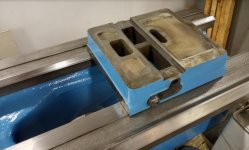
185.jpg

Using that base, maybe build a bridge across it. As you stated, I want multiple indicators. While I have not measured off it yet, underside of each way, the bed has been ground. How accurate to ways I'm not sure, but a potential reference, also might use it to support/add stability to bridge across TS base:
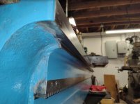
369.jpg

My first goal for the bed and using indicators would be to know I could tram back and forth consistently. Start at head stock end and indicate off un-wore, first 6" of way. Set indicator to zero. Tram to far end. I want to see zero at last 6" of TS end. Then tram back to head stock end. Again I want to see zero on indicator on return tram. If I can consistently tram back and forth, and always return to zero, then I think I can tram a grinder.

Use outer diameter of grinding wheel, just like a surface grinder. I wouldn't worry too much about grinding wheel wear. Your first main passes will be to lower the good/un-wore portion of ways to the lowest wear point of damaged way sections. With your final passes sparking out, just barely kissing the surface. Prior to hitting power button on the grinder, you could run test trams back and forth to ensure wheel is the same clearance on both extreme ends of bed.

Go nice and easy on each grinding pass, cutting between .00025" to .0005". Gradually working down to the valley of the worst wear. Set up to use electric wire cable hoists to pull tram both directions.

I would want to keep track of how much material removed. But in my head its almost irrelevant. Its a given the bed has wear, the carriage has more wear. So the carriage will have to be raised. But we don't know the number of how much it needs to raised. We wont know that number until ways are cut, and. . . with saddle, apron, lead screw etc mounted. We can shim/feeler gauge up the carriage until lead screw is centered in apron. And with those feeler gauge numbers, we have a real good number of what to add to raise carriage.

The real key is being able to tram consistently and stable. If I can, I feel absolutely confident I can make improvement over current way wear. Will I be splitting tenths of a thou, probably no. But I'd bet you a dollar I could get inside .001-002" over a substancial length.
 
One thought is with a long machinists straight edge and feeler gauges, you could check the tailstock ways on the bed to at least be sure they're not substantially out in any one place before using them as a reference.
 
Ideally the grinder would sit in the center of the tailstock base to get the best averaging effect. But to actually have clearance to grind the ways you probably need to set the grinder bracket on the headstock side of the base. Given most of the wear is going to be near the headstock, the headstock probably needs to come off.

I do agree that getting 3/4 of the accuracy restored is a worthwhile improvement. Emory cloth works well for the few cases where you need to get better tolerances
 
Ideally the grinder would sit in the center of the tailstock base to get the best averaging effect. But to actually have clearance to grind the ways you probably need to set the grinder bracket on the headstock side of the base. Given most of the wear is going to be near the headstock, the headstock probably needs to come off.

The guides for proper grinder guidance need to be longer than the total "working" stroke, not shorter. Not possible, but one can get a LOT closer than a short-arse TS base.

Good points from both of you. I do think the headstock has to come off. Though I think the grinding wheel would have to be oriented toward tail stock end, of the TS base, if it is indeed the guide, or tram.

Because Thermite has a point, you need longer travel. But Rabler's point of removing headstock solves that. Start the beginning of tram with TS base sitting where headstock normally is. Contact point of grinding wheel just in front of the TS base, or toward TS side of lathe.

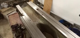
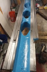
I currently have headstock sitting on the lathe. But here's some pics of the bed with headstock removed. Note the location of where carriage vee way begins. With headstock removed the tram can start prior to that point. Then run the entire length of bed and grinding wheel contact point will clear the far end just as tram reaches the end, allowing TS base to remain in full contact with bed.

112.jpg 114.jpg

If this all works out to reality, I would probably begin carriage flat way at the same position as its mating vee way.
 
A fabricated sled makes sense in my mind in that you can make something that has clearance to put the grinding component in the middle of the sled, rather than sticking off the front or back end. There is a reason road graders are long with the blade in the middle of that span. You average out variations, whereas if the blade is in front of or behind, you tend to amplify those variations.

As for making the sled long, you run into the problem that the sled can only run so far before going off the end of the bed and losing reference. As you slide the sled along the bed, it can really only slide the length of the bed minus the length of the sled. Maybe a little longer if you cheat by sliding the end of the sled past the length of the bed, but as soon as you do that you defeat the purpose of a longer sled. You could move the grinder point from the front to the back of the sled to get around this, but you're back to the issue above.
 
I know Bill has 2 10ee's, so he might be slightly biased in his mental planning for those :D. Shorter bed, smaller tailstock. . . So if what he's hinted at a couple times I'm guessing overhead rails or a gantry of sorts. Would be easier with the shorter bed, shorter distance. . . to use something and make it rigid. Plus the 10EE TS is quite a bit smaller.

The op,idacal, has 132" between centers. My bed is listed at 54" between centers, but length of carriage vee way is just north of 88". Hard for me to conceive covering those distances more accurate then what I could do with my own bed, outside of a real bed grinding service.

The TS base on my Series 61 is 12.25" along the ways, 11.25" across the ways, and 3 plus inches high, and heavy. I don't want to balance everything on it, but as a basic guide, maybe feasible. Could potentially add length in either direction with a 1/2" to 1" plate bolted on top with some spacers scraped in at the edge of the extension, to ride along ways as well.

Might even consider a sort of outriggers across to touch on outer ways for some rigidity/stability.
 
im sure it could be done, but Im not the person to do it. it would be a huge project in the shop when I already have a lot to do. its interesting listening to people who understand the theory and have done this kind of work though. would you use a cbn wheel on the grinder or standard wheels and keep dressing them? I do have an older gear machine thats a lot smaller that I would like to try tightening up. but I can't be without even a sloppy lathe for hundreds of hours worth of spare time. but thanks for all the advice. I learned a lot about this. I attempted to read connellys book, need more discipline than I have just to read the book.
 
im sure it could be done, but Im not the person to do it. it would be a huge project in the shop when I already have a lot to do. its interesting listening to people who understand the theory and have done this kind of work though. would you use a cbn wheel on the grinder or standard wheels and keep dressing them? I do have an older gear machine thats a lot smaller that I would like to try tightening up. but I can't be without even a sloppy lathe for hundreds of hours worth of spare time. but thanks for all the advice. I learned a lot about this. I attempted to read connellys book, need more discipline than I have just to read the book.

I'm in a bit of a different position than you or others where your lathe is still complete and operational. Mine is still in many pieces :D. The only real back tracking I need to do is unbolt the head stock and set it on the floor.

Being that close to be able to run some experiments, I think why not ? It doesn't mean I'm going to hit the power button and start grinding :D. But I think I can run tests with indicators and such, and get a better feel if it is feasible.

I think it may be feasible. If so might even try a test run on the non-essential flats that sit between the working ways. I was thinking using an AO wheel and dressing. But if I actually do test runs, might experiment with a couple different wheels to see finish.
 
Another thought: I have seen a few projects with hardened ways where the guys used the "grind-scraping* method. In other words, rather than trying to scrape with a scraper they just used an abrasive disk grinder and gentle little grinds as though they were using a scraper. Still used the same tried and true spotting and checking against references. Seemed to work out pretty decently for them as I recall. Just another arrow in the quiver of possibilities to consider.


Back
Top