NateA2
Cast Iron
- Joined
- Sep 4, 2012
- Location
- Ann Arbor MI.
I recently sold sold my CHNC to a friend. I wanted to replace it with a 10ee to convert to CNC.
I bought a used 10ee #41169 that was located in Long Island. I made the drive from Ann Arbor MI to Long Island this last weekend and picked the new 10ee up. LONG DRIVE! Seller was great. Got loaded safely and with care (thanks to his guys)
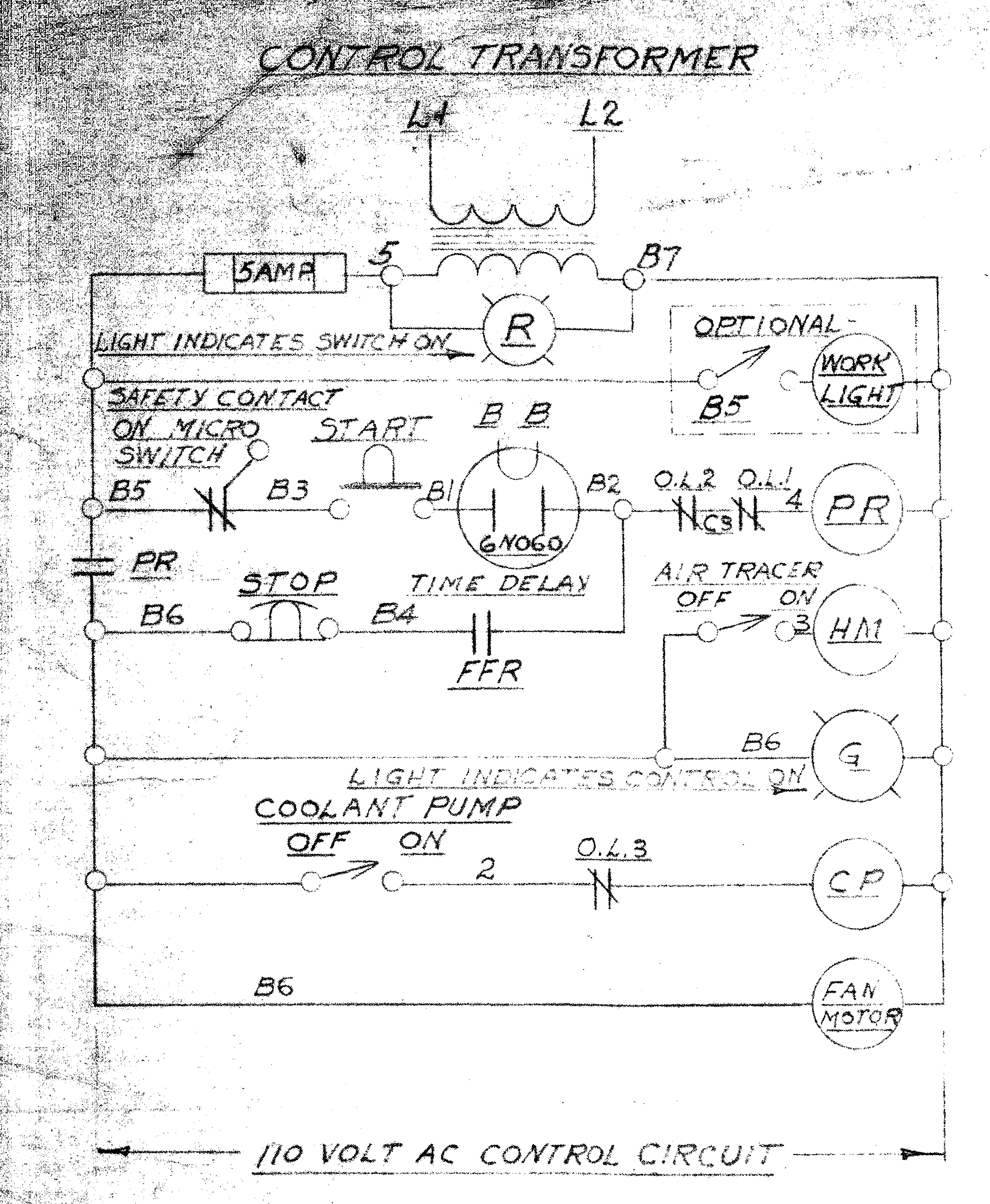
I have a call in to Monarch for a schematic and info on this AGT 10ee.
The AGT unit is long gone. This lathe not having a swiveling compound is immaterial to me as this machine is going CNC.
Looks like it is a mostly complete square dial 10ee. Appears to have all of the normal functionality of a non AGT 10ee save for the swiveling compound.
given that the AGT unit is gone, and that I dont see a contactor anywhere including in the cover on the rear of the headstock, I suspect that to wire up this machine to power I will need a contactor. I have a spare MG contactor from another 10ee, I believe its 220V and I have a 20HP RPC to power this new used lathe.
Am I correct that I will need a contactor?
The DC motor appears to be a 6 wire. Double windings for the WIAD drive?
I am reasonable fammilar with MG 10ee's and currently my primary lathe is a 1942 10ee MG.
I am missing one tube. a 6N060. I believe I can find one on ebay NOS.
Can anyone explain to me how power may be applied to this machine. I believe that the AGT unit contained a contactor but then again, you folks would certainly know better than me!
I have seen some brief mention of AGT 10ee's in this forum and online elsewhere, but nothing substantial. I am hoping some of you will find this AGT lathe interesting!
hoping that some of you will have some input here that can point me in the right direction!
Please see the pics below. Better pics will follow soon once I drop this machine down into my basement shop (remove kitchen floor plug and lower down into shop from outside house- I do this regularly as a few of you will know!)
Thanks for looking and I look forward to discussing this AGT 10ee.
Nate in Ann Arbor MI.


I bought a used 10ee #41169 that was located in Long Island. I made the drive from Ann Arbor MI to Long Island this last weekend and picked the new 10ee up. LONG DRIVE! Seller was great. Got loaded safely and with care (thanks to his guys)
I have a call in to Monarch for a schematic and info on this AGT 10ee.
The AGT unit is long gone. This lathe not having a swiveling compound is immaterial to me as this machine is going CNC.
Looks like it is a mostly complete square dial 10ee. Appears to have all of the normal functionality of a non AGT 10ee save for the swiveling compound.
given that the AGT unit is gone, and that I dont see a contactor anywhere including in the cover on the rear of the headstock, I suspect that to wire up this machine to power I will need a contactor. I have a spare MG contactor from another 10ee, I believe its 220V and I have a 20HP RPC to power this new used lathe.
Am I correct that I will need a contactor?
The DC motor appears to be a 6 wire. Double windings for the WIAD drive?
I am reasonable fammilar with MG 10ee's and currently my primary lathe is a 1942 10ee MG.
I am missing one tube. a 6N060. I believe I can find one on ebay NOS.
Can anyone explain to me how power may be applied to this machine. I believe that the AGT unit contained a contactor but then again, you folks would certainly know better than me!
I have seen some brief mention of AGT 10ee's in this forum and online elsewhere, but nothing substantial. I am hoping some of you will find this AGT lathe interesting!
hoping that some of you will have some input here that can point me in the right direction!
Please see the pics below. Better pics will follow soon once I drop this machine down into my basement shop (remove kitchen floor plug and lower down into shop from outside house- I do this regularly as a few of you will know!)
Thanks for looking and I look forward to discussing this AGT 10ee.
Nate in Ann Arbor MI.