What's new
What's new

New Set of 10EE Knobs

DaveE907

Titanium
Joined
Sep 18, 2007
Location
Spanish Springs, NV
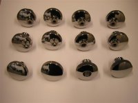
All of the zinc alloy knobs on my 1952 MG Square Dial were in poor cosmetic condition and some of them were mechanically damaged at their shaft joints from long use or mishap. I decided to make a new set from stainless steel. There are thirteen in all and there are six individual designs among them so the first step was to measure them all to sketch them up.

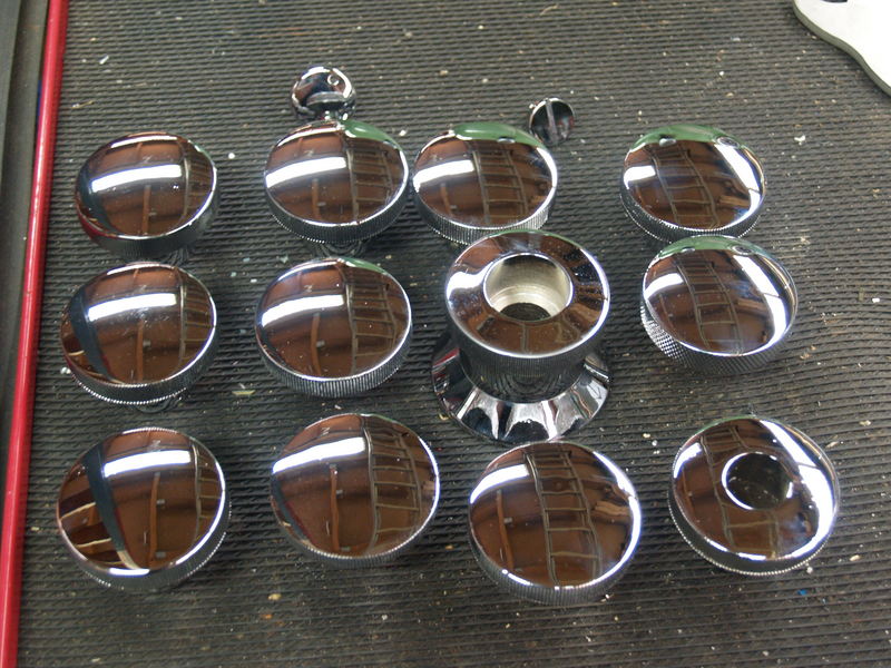
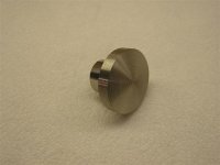
To ease machining I used 303 stainless. To reduce material cost they were made in two pieces, the knob body one piece, the shank another then assembled with a high strength anaerobic retaining compound. There's no radius at the knob to shank joint, otherwise these knobs generally conform to the original shape and size.

It was a simple project but will add significantly to the look and feel of this old iron. Only twelve show in the photos, the first one was made as a prototype for the apron assembly I posted awhile back.
 

Attachments

  • Monarch 10 EE 7-08 030 (Small).jpg
    Monarch 10 EE 7-08 030 (Small).jpg
    40.1 KB · Views: 450
  • Monarch 10 EE 7-08 044 (Small).jpg
    Monarch 10 EE 7-08 044 (Small).jpg
    30.3 KB · Views: 442
  • Monarch 10 EE 7-08 061 (Small).jpg
    Monarch 10 EE 7-08 061 (Small).jpg
    32.3 KB · Views: 422
  • Monarch 10 EE 7-08 063 (Small).jpg
    Monarch 10 EE 7-08 063 (Small).jpg
    33.3 KB · Views: 413
They look terrific; no, better than terrific.

Keep in mind that I'm a mechanic, not a machinist (trying to learn though...) so this may qualify as a stupid question: how did you do the radius on the face? It looks like from your pictures that you turned a taper first; did you freehand the curve?

Travis
 
Dave your knobs look great.
Last Friday I got mine back from rechroming at a chromingshop in the neighborhood. They were in the same sorrow state as the ones from Dave (I think they were even worse.)

knoppenchroom.jpg


The little specs on the chrome is dust.
My point here is that although the surface is scratched and has little dimples often they can be made nearly new by these guys.
 
Thank you for the kind comments.

The 4.0 in. radius convex surface was generated by step turning which the photos below show. It involves calculating the diameter to turn to at chosen step intervals along the Z axis that conform to the desired curvature, here the steps are .005 in. each. The corner of the tool generates circles which lie on the desired part surface.

After turning quick work on a flexible abrasive belt while spinning the part is the next step to bring the surface to the intersection of the plane and cylindrical surfaces at each step. The third photo shows half of the knobs after this step with the others ready for the belt. They are then ready for polishing.

Yoyo, your chromed knobs look super. I considered having the old knobs plated but some of them were too far gone. Some had been hit hard enough to eliminate the knurling, others had been gouged with a disk grinder and two no longer even fit their shaft or taper pin. I decided the best thing that I could do myself was make new ones.
 

Attachments

  • Monarch 10 EE 7-08 032 (Small).jpg
    Monarch 10 EE 7-08 032 (Small).jpg
    45.8 KB · Views: 329
  • Monarch 10 EE 7-08 035 (Small).jpg
    Monarch 10 EE 7-08 035 (Small).jpg
    32.8 KB · Views: 318
  • Monarch 10 EE 7-08 045 (Small).jpg
    Monarch 10 EE 7-08 045 (Small).jpg
    29 KB · Views: 339
Very nice work Dave! The knurling is very well done. Did you do the work on the 10EE?

The shank on the spindle lock on mine is much smaller than the rest of th knobs. Is that true on your machine as well?

Cal
 
My 10EE is apart while I work on it. Did the knobs on a Takasawa TSL I've had for about 30 years. The knurls were gashed, one notch at a time, it gave the best results with what I had on hand in the 303. It sounds worse than it was, 160 teeth, 9 minutes per knob on a manual turret mill with a dividing head. Who says machining can't be exercise?

Yes, on this square dial the spindle lock knob has a .615 in. dia. shank which is smaller than the nominal 1.25 in. dia. shanks of most of the other knobs. The headstock upper cover latch also has a .615 in. dia. shank size but differs in the thickness of the knob body. Then the apron has a nominal .75 in. dia. shank with a thin body.

There are six unique designs among the group of knobs, it's just a matter of making them to match the originals.
 
Dave, very nice work. Do you have a DRO on the takisawa, or did you do all the stepping using the dials? That kind of work takes a lot of patience and it is easy to screw up. Your careful work is a pleasure to see.

-Dave
 
Thanks guys.

Gary, it takes some number crunching to determine the tool positions to generate a contour. CNC machines do it seamlessly, humans have to work at it.

The calculations are done once the part contour is described by an equation. For circular arcs it's R**2 = X**2 + Y**2 in math terms. Here one knows R and X, you choose the increments on the X axis (relates to carriage position on the Z axis in lathe terms) so solve for Y and double it for diameter. You'll generate a table of numbers you can then translate to what you need to operate the machine. I make a table of carriage positions and crossfeed dial numbers which take into account the crossfeed screw pitch and for this part set the carriage position as "zero" at the part maximum length. The crossfeed is zeroed to make integer inch diameter at zero to agree with the table numbers I made.

Next is just cranking, hitting the numbers and trying to avoid chip burns. Three minutes per part, it was fun.

Dave, no DRO on the Takisawa, the crossfeed dial and Trav-A-Dial have served well. Never warmed up to DRO on a lathe.
 
Look beautiful Dave. Too nice. Now you will have a hard time making the rest of the machine look as good! :D
 
Another way to do this, what I call my blood sweat and tears tracer, is to turn a piece of metal to a dia. of 8"(for a 4" radius). It should be at least 1/4" thick or thick enough that an indicator tip can track it.

Then locate this disk on the bedway, head stock or even the tailstock or someplace that doesn't move. This can be done using clamps, blocks or whatever it takes, just remember that the part of the radius you use must correspond to the radius you want to cut and has to be placed with sufficient space for an indicator to track while observing it.

It(the disk) needs to be horizontal so that an indicator tip can track the radius while the magnetic base for the indicator is mounted on the cross slide.

With the tip of the tool located on the axis of rotation of the work and near the work, place the indicator tip on the high spot of the radius of the disk. Put a convenient amount of pressure on the indicator and zero it.

While the cross slide feeds, try to keep the indicator needle still(not moving) by using the carriage hand wheel with both hands. Its best to step it out by keeping the needle .010" or so away from zero. This way leaves you a small finish cut.

A little practice and common sense is helpful here.

You can also do angles this way.

This is not for precision work.

Jim W.
 
why not take it one stop further


instead of a pointer on your indicator ,use a solid pointer fastened to the cross slide which bears on the disc you have fixed .

hold the saddle with the apron wheel so that the pointer presses on the disc ( start with the slide out ) advance the slide keeping the pressure on the apron wheel, the tool will then follow the profile of the disc ( or what shape that you have)


its quick and dirty but it does work , and is repeatable
 
That's more like one step shorter by eliminating the indicator.

That would work providing you can control the pressure on the template, otherwise it's easy to move the template(disk). An indicator acts as a buffer to ensure against placing any pressure on the template.

I suppose you could affix the disk template more rigidly so that it wouldn't move and use a solid pointer as you describe and hang a heavy weight over a pulley so that constant pressure is applied to the template, but then you would have one of these.
10EEformingattachment.jpg


Jim W.
 
Jim, that is about the coolest round dial accessory I have ever seen, and had no idea existed. It is like an early version of the hydraulic tracing attachment, except that it uses gravity instead of hydraulics to follow the template, and it doesn't get in the way of normal lathe operation.

What is the book that the picture is taken from? Are there other equally interesting photographs in that book?

-Dave
 
Haven't seen one of those Monarch tracer accessories for over 40 years and never saw one set up and in use. It's great to a see photo of one on the lathe, thanks for posting it.

Good points on tracer improvisations, have done some of them too. Tweaking tracer templates with an optical comparitor was a long ago pleasure. For precise tracer work it's important that the stylus (or indicator tip) and the tool radius be the same if the contour is other than a straight taper.

Another way to make a relatively large radius such as this knob face on a manual lathe is with a rod with pivots on both ends. One end is fixed to the bed, the other to the cross slide. The pivots can be as simple as a conical holes with rounded ends on the rod. The distance between centers of rotation of the rod ends is the radius produced. Keep the carriage biased to compress the rod while moving the cross slide. Takes a bit of setup to get the center of rotation spot on, then it'll crank out spherical surface workpieces no problem.
 
Pant, drool...

"What is the book that the picture is taken from? Are there other equally interesting photographs in that book?"

Me too; got to know what's on the other pages!

Travis
 
Last edited:
10EE attachments

"That book" is an insert that was included in my manual for a 1961 10EE manufacturing modular lathe with an air gage hydraulic tracer.

There are many attachments included in this insert, the vast majority have appeared at one time or another on this forum.

Here are some pictures that I don't believe I have seen here before. I believe there is enough description in the pictures with the first picture being the front cover of the insert.

10EEattachments001.jpg


10EEattachments002.jpg


10EEattachments003.jpg


10EEattachments004.jpg


10EEattachments005.jpg


10EEattachments007.jpg


10EEattachments008.jpg


10EEattachments009.jpg


Jim W.
 
Jim, thanks for posting - that is a very interesting catalog. Is there a date code on the back cover? Most Monarch publications had a two digit year and sometimes the month.

So the often speculated ball-turning rest actually exists, or at least a prototype of one did.

Peter, have you ever seen the patent papers for that accessory? It certainly looks like Monarch engineering at full strength...

Does anyone on this forum actually own one or have seen one?

-Dave


Back
Top