What's new
What's new

Fixing square-dial 10ee oil leaking past EE-2888

ee_chris

Aluminum
Joined
Apr 9, 2003
Location
Derwood, MD
Hi all,

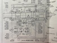
I have the spindle out of my 1946 10ee in order to apply sealant under the EE-2888 bushing and reinstall. Oil was leaking pretty quickly from the left bearing compartment to the center one. Many thanks to everyone who posted info here on spindle removal. I attached a photo of part of drawing 202268, which I believe is correct for this machine.

It isn't clear to me what the next steps are. Some specific questions:

1. Just to confirm, the best fix for this leak is to remove EE-2888 and apply sealant between it and the headstock. Correct? The remaining questions assume this is the case.

2. The gear that rides in EE-2888 (EE-2110) looks from the drawing to be retained by a ring held on the gear by set-screw(s). So EE-2888 has to come out with the gear in it? If this is the case, does the idler gear below interfere, and if so how do you get it out of way? And should the selector fork (EE-1102) also be removed?

3. I've read the rear bearings shouldn't be removed until after EE-2888 is out, and I'd prefer not to touch them at all. If so, how do you extract EE-2888? The shoulder is in a counterbore, and its ID is larger than the ID of the rear bearing. The retaining set-screw in top was already removed, and with a pin-punch in the oiling hole I can wiggle the bushing in rotation already. Should it just slip out?

4. Is EE-2888 located such that it can be reinstalled and the sealant allowed to cure before the spindle goes back in? Or does the spindle have to be reinstalled before the sealant sets so the gear and bushing self-center on the spindle?

I would really appreciate some guidance from folks who have been through this before. I am hoping to fix the leak without creating any new problems. :)

Thanks,

Chris

IMG_4887_small.jpg
 

Attachments

  • IMG_4887.jpg
    IMG_4887.jpg
    19.8 KB · Views: 38
Last edited:
Chris, you're over thinking this. The correct path to remove everything will be clear once you start doing it.

Yes the shifter has to come out and then you can loosen the setscrew that holds the plate on the idler shaft, then the plates and idler gear will slide an inch or two towards the front of the spindle. There is also a small rack gear on the bottom of the idler shaft that needs to come out, it is held by a pin and the capscrews that hold the shift fork on.

However, the more important question is why? Do you REALLY want to put sealant in there? Do you have another lathe? If so, a better solution, if that gap is really the source of the leak, is to machine an o-ring groove in the outside of the bronze bushing.

Before you do anything I suggest that you remove EE-2888 then fill the reservoir with oil, let it sit and see if you perhaps have a pinhole. If that checks out, then do the o-ring and reinsert EE2888 and again fill the reservoir, this time to the sight glass oil line level and check again.
 
Rimcanyon, thanks for the details about disassembly! I do tend to over-engineer things, but I really want to fix it the first time. :)

These threads mention the exact same problem (one in a round-dial with different PNs but the same layout):
- In this thread Cal Haines suggested the factory probably used some kind of sealant that failed over time.
- In post #47 here there is a picture showing where jgnichol used sealant, and in post #48 AlfaGTA discusses adding an O-ring like you suggested.

I like the O-ring idea. I'm thinking a properly-fitted O-ring would be less likely to fail than a very thin film of sealant.
 
On my '56 the bearing sumps leak into the main headstock sump, but it's not completely the fault of EE-2888. I surmise this because the leak from the front sump can be mitigated by stopping the lathe with the #2 camlock cam on the top position. Since EE-2888 isn't turning the leak has something to do with the spindle, perhaps a scratch along it or something.

BTW: I just live with the leak. It helps me keep the bearing oil sumps full of fresh clean oil.
 
There is another oil leak path you might want to investigate. If there is a scratch under the rear main bearing (or if your rear main bearing has the ball insertion notch in the wrong place), oil can get to the oil slinger drain hole on the outside. That drain hole goes through the end web on the headstock and empties into the center cavity. Also is your lathe level front to back? Just a small change in level can affect the apparent oil level, it is like a level vial. When I assembled the 49 lathe the oil would quickly drop below the oil line. Adding a ¼" shim under the rear headstock solved the problem.

Make sure the end pulley is tight against the oil slinger when you reassemble.
 
There is another oil leak path you might want to investigate. If there is a scratch under the rear main bearing (or if your rear main bearing has the ball insertion notch in the wrong place), oil can get to the oil slinger drain hole on the outside. That drain hole goes through the end web on the headstock and empties into the center cavity. ...
Dave,

Looking at one of your headstock photos:
IMG_0398.jpg
I assume that you're referring to the left-hand hole of the pair at 6 O'clock. Are you saying that hole drains into the cavity with the rear bearing oil sight glass, or into the center of the headstock itself?

Cal
 
Dave,

Looking at one of your headstock photos:
View attachment 347374
I assume that you're referring to the left-hand hole of the pair at 6 O'clock. Are you saying that hole drains into the cavity with the rear bearing oil sight glass, or into the center of the headstock itself?

Cal

It drains into the center of the headstock, the path goes below the rear main bearing oil reservoir. But I bet it is close, so that is why I suggested checking to see if the reservoir holds oil.
 
It drains into the center of the headstock, the path goes below the rear main bearing oil reservoir. But I bet it is close, so that is why I suggested checking to see if the reservoir holds oil.
Well, that changes everything... (I had no idea that oil return path was there.) That certainly makes it a prime candidate for rear bearing oil leaks. It doesn't show up on any of the headstock section drawings. Even though the A-B-C-D-E section line zigzags around, it still passes right through the area in question. The single-reservoir headstock drawing, 202.268 shows the oil return passages for the front bearing, but not for the rear.

I asked Hobby Racer to check his headstock and he has the passage as well. His is drilled at a pretty good angle, coming out an inch or two behind the centerline of the spindle, but appears to be more or less horizontal.

Thanks Dave!

Cal
 
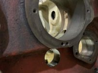
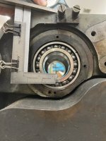
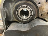
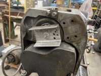
I took some pictures that show where the oil level in the left bearing compartment should be (1946 10ee w/3 sight-glasses). I measured 5" from the flat where the top cover attaches down to the center of the left sight-glass bore, which should be the oil level in the bearing compartment. Here is where that transfers to the end bearing looking at the inside and outside (bottom of the small square).
IMG_5002.jpgIMG_5006.jpgIMG_5009.jpg
The bearing end cover on my lathe has an ID that is about 0.590 above the bottom of the bearing bore. This well above where the oil should be, looking at the second picture above, and falls part-way up the inner race. Curiously, the slinger on my lathe isn't part of the spindle lock. It is a separate part. The drawings I posted earlier were provided by Monarch for my 1947 machine, so perhaps there was a change. The drain hole in the end cover returns to the center compartment through the hole under the bearing bore discussed in earlier posts.
IMG_4902.jpgIMG_4903.jpg

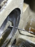
Above that return hole for the bearing cover, this lathe has an overflow hole drilled up at an angle from the center compartment into the bearing compartment. It is about 0.156 diam. and breaks out into the pocket for the shoulder of EE-2888. There is sufficient clearance so the spot that broke out clears the OD of the bushing. In the second pic below, you can see the bottom of the drill bit inserted into the overflow hole looking through the sight-glass bore.

I had trouble getting a picture (for lack of extra hands), but using my scale setup, I confirmed that the bottom of the overflow hole where it intersects the sight glass bore is *below* the sight-glass oil level by about half the diameter of the drill bit. So it will always drain into the center compartment down to that level if the oil is filled to the sight-glass line. This will bug me forever, so I'm thinking about epoxying a thin-wall tube into the hole to bring the overflow level up to the sight-glass midline.
IMG_4998.jpgIMG_5001.jpg
It is also worth noting that if the lathe isn't level and tilts downwards even a little in the rear, this will cause oil to drain to the center compartment.
 
Last edited:
When the lathe isn't running, there doesn't appear to be any way for oil to get from the left bearing compartment to the center compartment except by leaking past the big bushing (EE-2888). I'm ignoring the overflow hole being too low as described above. That would only account for oil draining down by perhaps 0.1", and mine drains almost completely. So I'm going to install an O-ring in the bushing as suggested previously. Here is a picture of my bushing:
IMG_5014.jpg
There is already a groove about 0.125" wide and 0.030" deep next to the shoulder. Enlarging this slightly to fit an O-ring would seem to be my only option. There isn't enough width between the set-screw pocket and the existing groove to make a completely new groove (IMHO).

If I used a 0.103" cross-section O-ring, the recommended gland width is 0.142", which still clears the set screw pocket by ~0.050". The bushing OD is ~3.5433" (90mm), so (based on something close from a catalog) the groove should be cut to ~0.162" smaller diameter, or a groove depth of 0.081". I think a size -153 O-ring should fit with a tiny bit of stretch. It wouldn't go very far into the bore, but I think it should still seal. Any comments on this plan? Would 0.103" be a good O-ring cross-section to use?

EDIT: I forgot to reduce the OD by the groove depth, so a -153 is probably too large. I'm going to try a -152 instead.
 
Last edited:
I cut the O-ring groove. That cross-section O-ring so close to the edge of the bore didn't want to stay put, but after clamping the bushing in position overnight, the bushing set-screw seemed to hold it in fine when lightly snugged. The set-screw can't be really tight because it distorts the bore of the bushing and prevents the gear sleeve from turning.IMG_5023.JPEG
IMG_5024.JPEG

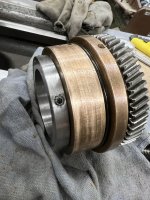
Here is the bushing with the gear and retaining collar reassembled. I used a big automatic center-punch to re-stake the set screws the way they appeared to have been staked at the factory.
IMG_5025.JPEG
 
Here is the bushing pulled into place with my makeshift puller. At first it didn't seem to want to stay put, but after being clamped in position overnight it stayed in place.
IMG_5035.JPEG
IMG_5036.JPEG
 
After I got the sight-glass cleaned up and reinstalled, I put some oil in, and it ran into the center compartment within a couple of minutes, stopping when the oil was well below the line. I was expecting it to be a little low because the overflow hole at the rear of sight glass bore was drilled too low (as described above). But not this low.

IMG_5045.JPEG

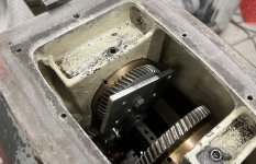
After some head-scratching, I managed to get better lighting inside the sight glass bore, and found something I missed before. There is *another* hole into the center compartment from the sight-glass bore besides the overflow at the rear. This one is hiding behind the gear at the front left of the center compartment. Here is a picture showing a piece of wire poking out from inside the sight glass bore.
IMG_5049.JPEG

Here is a crappy picture looking in the sight-glass bore. I highlighted the approximate centerline of the cross-hole in red:
IMG_5047_highlighted.JPEG

Here is a (crappy USB) borescope pic of that hole looking left. It is threaded, and there is the end of a bolt or plug visible.
WIN_20220530_11_19_52_Pro.jpg
And here is looking to the right, where the hole passes into the center compartment (where the wire pokes out in the pic above). That side is not threaded, and is not angled up like the overflow hole at the rear of the sight-glass bore.
WIN_20220530_11_20_10_Pro.jpg
 
I am at a loss as to why that cross-hole at the front would be there, or what is threaded into it from the left. The fastener or plug is hidden behind the top of the gearbox. Since the hole almost touches the bottom of the sight-glass bore, it renders that sight glass useless and makes the rear overflow hole redundant. I'm thinking it must be a fabrication or design error.

So I think I'm going to do this:
  1. Clean the front mystery hole area thoroughly, and use Permatex Gray to fill the left side where the fastener is visible and the through-hole into the center compartment on the right. I might use a plug of some kind on the right, but nothing that would do damage if it ever got loose.
  2. Raise the rear overflow level to make it correct vs. the sight-glass. I'll insert a short piece of 0.156OD 0.014-wall brass tube into the hole from the center compartment, and seal it with Permatex where it enters the sight-glass bore. I'll withdraw it until the top end is at the needed height.
  3. After ample cure time, I'll put the bushing back in and do another leak test to see if there are any other leak paths before reinstalling the spindle.
 
Last edited:
I am at a loss as to why that cross-hole at the front would be there, or what is threaded into it from the left. The fastener or plug is hidden behind the top of the gearbox. Since the hole almost touches the bottom of the sight-glass bore, it renders that sight glass useless and makes the rear overflow hole redundant. I'm thinking it must be a fabrication or design error.
...
When you say "behind the top of the gearbox", do you you mean behind the cover for the end gears? (See figure 7 and parts sheet 142 in the square-dial manual.) It could be that they drilled one of the mounting holes way too deep. I don't have a square-dial and I can't find good photos of the end gear housing on and off the headstock, so I'm not sure if there's supposed to be a fastener in that area.

Cal
Yes. I was referring to the housing labeled as EE2859 on sheet 142. I don't know what this looks like disassembled, but I don't think there is any connection to the headstock where my mystery hole is. I bent the end 2" of a piece of stiff wire at 90 degrees, and was able to sweep it across behind the gearbox in the gap between it and the headstock. If there was a fastener passing through, it would have interfered.


Back
Top