peterh5322
Diamond
- Joined
- Dec 15, 2002
- Location
- Monterey Bay, California
It is well-known that WiaD and Modular 10EEs may be powered by single-phase.
Herein I present a modification to Motor-Generator 10EEs which will allow these machines to be powered by single-phase. Both a 230 volt and a 460 volt modification are presented.
The underlying technology is adapted from Henry Steelman's U.S. Patent 2,922,942 (which see), and is extended by me to incorporate power factor correction (not claimed by Steelman in his patent) and easy adaptation to the 10EE's AC Section.
(An essential feature, and requirement of Steelman's idea is a twelve-wire three-phase motor, or a nine-wire motor which has been modified to add the three "missing" wires implicit in that motor's "star point", may be very easily powered by single phase, provided a starting circuit is provided and the motor winding components are wired in an innovative way. This innovation simulates a capacitor start/capacitor run single-phase motor. I have added power factor correction, which Steelman did not claim, and which further improves upon Steelman's idea).
The first Figure describes in the abstract how a three-phase motor may be powered by single-phase without sacrificing motor power. This is more-or-less directly from Steelman's patent, extended by information included in Steelman Industries, Inc's modification to that patent for 460 volt applications.
The second Figure describes the 10EE AC Section, with all loads except for the "three-wire control station" removed, and with each terminal to which the converted motor and its support circuitry is to be connected.
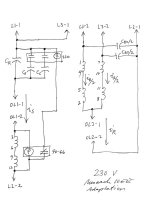
The third Figure shows details the 230 volt modification, showing how each part of the motor-generator, and the additional starting and power factor correcting circuits are to be integrated into the AC Section. The 90-66 potential relay coil is across the entire start winding. The run windings are split across two poles of the magnetic motor starter thereby reducing the stress on the Size 1 starter. There are two power factor correcting capacitors, corresponding to each pole of the starter. As is required by the NEC, the capacitors are placed after the disconnecting means, and before the motor protection means. Bleeder resistors are not shown for clarity.
The fourth Figure shows details the 460 volt modification, showing how each part of the motor-generator, and the additional starting and power factor correcting circuits are to be integrated into the AC Section. The 90-66 potential relay coil is across one-half of the start winding. Each capacitor shown is actually two identical capacitors in series.
I have not detailed the values of the capacitors. Clearly, the run capacitors must be 370 VAC, minimum (740 volts when placed in series for 460 volts), and the start capacitors must be 250 VAC, minimum (500 volts when placed in series for 460 volts).
Initial values for C may be obtained from
I = 2 * π * F * C * V
where I is the FLA in Amperes, π is the constant 3.14, F is the frequency in Hertz (the factor 2π converts this frequency from Hz to radians/second), C is the capacitance in Farads, and V is the voltage in Volts.
Final values for each C may be obtained by tuning.
References:
1) Henry A. Steelman's patent
http://www.pat2pdf.org/patents/pat2922942.pdf
2) Steelman Industries Inc installation information for Steelman's H.A.S. converter
http://www.capacitorconvertors.com/pdf/staticinstructions.pdf
Recommended initial values for Cr are 11.53 µF per FLA amp for 230 volts and 5.77 µF per FLA amp for 460 volts. Use a clamp meter to ensure the current in the start winding doesn't exceed FLA amperes.
Recommended initial value for Cs is ten times the value of Cr, tuning for starting in two seconds or less.
Recommended initial value for Cpf is 0.1 times the value of Cr, tuning for just under minimum current, on the under-compensated side of 1.0 P.F.
Herein I present a modification to Motor-Generator 10EEs which will allow these machines to be powered by single-phase. Both a 230 volt and a 460 volt modification are presented.
The underlying technology is adapted from Henry Steelman's U.S. Patent 2,922,942 (which see), and is extended by me to incorporate power factor correction (not claimed by Steelman in his patent) and easy adaptation to the 10EE's AC Section.
(An essential feature, and requirement of Steelman's idea is a twelve-wire three-phase motor, or a nine-wire motor which has been modified to add the three "missing" wires implicit in that motor's "star point", may be very easily powered by single phase, provided a starting circuit is provided and the motor winding components are wired in an innovative way. This innovation simulates a capacitor start/capacitor run single-phase motor. I have added power factor correction, which Steelman did not claim, and which further improves upon Steelman's idea).
The first Figure describes in the abstract how a three-phase motor may be powered by single-phase without sacrificing motor power. This is more-or-less directly from Steelman's patent, extended by information included in Steelman Industries, Inc's modification to that patent for 460 volt applications.
The second Figure describes the 10EE AC Section, with all loads except for the "three-wire control station" removed, and with each terminal to which the converted motor and its support circuitry is to be connected.
The third Figure shows details the 230 volt modification, showing how each part of the motor-generator, and the additional starting and power factor correcting circuits are to be integrated into the AC Section. The 90-66 potential relay coil is across the entire start winding. The run windings are split across two poles of the magnetic motor starter thereby reducing the stress on the Size 1 starter. There are two power factor correcting capacitors, corresponding to each pole of the starter. As is required by the NEC, the capacitors are placed after the disconnecting means, and before the motor protection means. Bleeder resistors are not shown for clarity.
The fourth Figure shows details the 460 volt modification, showing how each part of the motor-generator, and the additional starting and power factor correcting circuits are to be integrated into the AC Section. The 90-66 potential relay coil is across one-half of the start winding. Each capacitor shown is actually two identical capacitors in series.
I have not detailed the values of the capacitors. Clearly, the run capacitors must be 370 VAC, minimum (740 volts when placed in series for 460 volts), and the start capacitors must be 250 VAC, minimum (500 volts when placed in series for 460 volts).
Initial values for C may be obtained from
I = 2 * π * F * C * V
where I is the FLA in Amperes, π is the constant 3.14, F is the frequency in Hertz (the factor 2π converts this frequency from Hz to radians/second), C is the capacitance in Farads, and V is the voltage in Volts.
Final values for each C may be obtained by tuning.
References:
1) Henry A. Steelman's patent
http://www.pat2pdf.org/patents/pat2922942.pdf
2) Steelman Industries Inc installation information for Steelman's H.A.S. converter
http://www.capacitorconvertors.com/pdf/staticinstructions.pdf
Recommended initial values for Cr are 11.53 µF per FLA amp for 230 volts and 5.77 µF per FLA amp for 460 volts. Use a clamp meter to ensure the current in the start winding doesn't exceed FLA amperes.
Recommended initial value for Cs is ten times the value of Cr, tuning for starting in two seconds or less.
Recommended initial value for Cpf is 0.1 times the value of Cr, tuning for just under minimum current, on the under-compensated side of 1.0 P.F.
Attachments


Last edited:
