What's new
What's new

Square Dial Gearbox Removal

DaveE907

Titanium
Joined
Sep 18, 2007
Location
Spanish Springs, NV
Gearbox removal has been addressed before but there were errors in some of the texts along with a lack of photos depicting what was being talked about. I recently removed the gearbox from my 10EE square dial for some work and thought it might be worthwhile to document the process. Hope someone finds it useful.

There are a number of photos so to be kind to those of us without broadband they're posted as attachments. Click on any you want to see a larger version of. Due to forum limitations this will continue for multiple posts.

These steps do not have to proceed in the exact sequence I used but they need to be accomplished to get the task done.

1) Remove belt idlers, feed belt and spindle drive belts.

2) Disconnect leadscrew and feed rod from gearbox, withdraw ELSR rod if so equipped.

3) Drain gearbox oil (optional at this point but highly recommended).

4) Remove the taper pin holding the upper speed control sprocket to its shaft, slide it off the shaft and remove the chain. Pull on the speed control knob to extract the shaft.

5) Remove the backgear linkage rod.

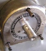
6) Use a face spanner to remove the screw holding the Thread/Feed knob to the headstock, remove the spring, pull knob off shaft and remove the woodruff key from the shaft.

7) Remove the three 1/4-20 SHCS holding the housing to the headstock and the housing pulls straight off.
 

Attachments

  • Monarch 10EE Gearbox 1.jpg
    Monarch 10EE Gearbox 1.jpg
    79.3 KB · Views: 494
  • Monarch 10EE Gearbox 2.jpg
    Monarch 10EE Gearbox 2.jpg
    46.1 KB · Views: 467
  • Monarch 10EE Gearbox 3.jpg
    Monarch 10EE Gearbox 3.jpg
    20.7 KB · Views: 456
  • Monarch 10EE Gearbox 4.jpg
    Monarch 10EE Gearbox 4.jpg
    77.9 KB · Views: 924
  • Monarch 10EE Gearbox 5.jpg
    Monarch 10EE Gearbox 5.jpg
    82.4 KB · Views: 847
8) Remove the four 8-32 SHCS holding the interlock housing to the headstock, remove the housing, slider and its spring.

9) Now is the time to clean the exterior of the gearbox to the extent possible. The next steps open up its interior to contamination so it's important to clean off the top cover and the upper rear of the gearbox to prevent swarf and debris from falling into the gearbox. Careful use of compressed air will be helpful. I used a can of brake cleaner and paper towels to scrub things up.

10) Remove the upper right hand lever. Drive out its taper pin, remove the setscrew and it will pull off the shaft.

11) Remove the two 1/4-20 SHCS holding the bushing/lock detent assembly to the gearbox and pull the assembly off the shaft.

12) Pull the shaft straight out of the gearbox, it will come out easily.
 

Attachments

  • Monarch 10EE Gearbox 6.jpg
    Monarch 10EE Gearbox 6.jpg
    81.3 KB · Views: 490
  • Monarch 10EE Gearbox 7.jpg
    Monarch 10EE Gearbox 7.jpg
    93.1 KB · Views: 528
  • Monarch 10EE Gearbox 8.jpg
    Monarch 10EE Gearbox 8.jpg
    78 KB · Views: 504
  • Monarch 10EE Gearbox 9.jpg
    Monarch 10EE Gearbox 9.jpg
    77.4 KB · Views: 578
  • Monarch 10EE Gearbox 10.jpg
    Monarch 10EE Gearbox 10.jpg
    17.5 KB · Views: 467
13) Remove two 1/4-20 SHCS from the upper surface of the half-round top cover. Mine were buried under paint and filler, the photo shows where they're located. Remove the two 1/4-20 SHCS holding the cover end to the right end plate of the gearbox.

14) Pull the cover toward the front of the lathe and off the gearbox.

15) Remove the six 1/4-20 SHCS, the change gear cover and its gasket located under the spindle.

16) Remove the nut holding the upper gear, the washer, gear and felt ring behind the gear.
 

Attachments

  • Monarch 10EE Gearbox 11.jpg
    Monarch 10EE Gearbox 11.jpg
    63.3 KB · Views: 519
  • Monarch 10EE Gearbox 12.jpg
    Monarch 10EE Gearbox 12.jpg
    55.7 KB · Views: 539
  • Monarch 10EE Gearbox 13.jpg
    Monarch 10EE Gearbox 13.jpg
    92.3 KB · Views: 493
  • Monarch 10EE Gearbox 14.jpg
    Monarch 10EE Gearbox 14.jpg
    87 KB · Views: 891
  • Monarch 10EE Gearbox 15.jpg
    Monarch 10EE Gearbox 15.jpg
    55.9 KB · Views: 486
17) Remove the two screws and cover plate at the bottom front of the gearbox.

18) Remove the two 3/8-16 upper SHCS and the two lower 3/8-16 SHCS shown in the photos. Note the upper screws are shorter than the lower screws. The gearbox is now detached from the lathe and simply resting on the horizontal surface of the lathe base.

19) Slide the gearbox out parallel to the lathe axis onto a suitable work surface at the same height as the lathe base upper surface.

Warning! The gearbox is very heavy. I made a small work table on castors from scrap lumber just for this job as I work alone and won't be picking this heavy lump up by myself any time soon.

The last photo shows the seldom seen backside of the gearbox.
 

Attachments

  • Monarch 10EE Gearbox 16.jpg
    Monarch 10EE Gearbox 16.jpg
    76.8 KB · Views: 512
  • Monarch 10EE Gearbox 17.jpg
    Monarch 10EE Gearbox 17.jpg
    91.9 KB · Views: 553
  • Monarch 10EE Gearbox 18.jpg
    Monarch 10EE Gearbox 18.jpg
    59.5 KB · Views: 441
  • Monarch 10EE Gearbox 19.jpg
    Monarch 10EE Gearbox 19.jpg
    82 KB · Views: 747
  • Monarch 10EE Gearbox 20.jpg
    Monarch 10EE Gearbox 20.jpg
    75.8 KB · Views: 635
Dave,

Thanks for taking the time to post that. I'm sure the next guy will appreciate it!

Could you shoot a photo or two of the cavity where the gearbox sits. I've always been curious how that's laid out, particularly when it comes to drilling/tapping holes in the contactor enclosure.

Cal
 
As I remember, none of the bearings are unusual, and there's a bunch. At least they were a few years ago. :rolleyes5:
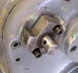
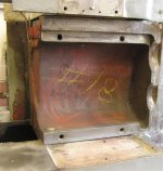
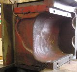
The two output shafts for the carriage drive use labyrinth seals. I replaced these with conventional neoprene lipped seals. I don't have a part# in front of me, but the shaft and housing size are standard, and they install perfectly. I painted the inside like the headstock with the Klink's tub and basin expoxy, which now after a few years imersed in oil, shows no sign of softening and is tough and shiny as the day I put it on.
 
Did I mention it's HEAVY?

With the assistance of my understanding wife I picked up the gearbox while she slid a scale under it today. It came in at 168 lb. :eek: Don't mess with one of these without preparation.

Cal, here are some photos for you. It was great to see marks made by workers on the line in Feb, 1952. They will stay. As you know this is a square dial, I don't how it differs from a round dial in this area. From a casual glance it doesn't look like there's much to run into by drilling into the back of the contactor enclosure other than the headstock hold down bolts and the oil overflow line for the center gear section of the headstock. Anything under .75" deep looks OK but can't imagine you'd go that deep anyway.

Thanks for the information Daryl. This gearbox is silky smooth and I don't anticipate any bearing replacements. A primary reason to pull it was to add seals to the output shafts as you describe. I used Klink's tub and basin epoxy in the apron, appreciate your observation of good service with it and a bow to Forrest Addy for his recomendation.

A visual and manual inspection of the gears shows all is well with them. I'm replacing all the shaft lip seals and packing, sealing up oil leaks, new gaskets, modern materials, no more drooling oil. :D

Other tasks include: removing, repairing and painting the aluminum plaques; prep and painting of the gearbox; fitting new stainless knobs; fitting new stainless ball end levers; powder coating the lever bodies, cleaning and flushing out the gearcase; measuring for a set of metric change gears to be made, etc.
 

Attachments

  • Monarch Gearbox  Mounting 1.jpg
    Monarch Gearbox Mounting 1.jpg
    79.9 KB · Views: 424
  • Monarch Gearbox Mounting 2.jpg
    Monarch Gearbox Mounting 2.jpg
    89 KB · Views: 418
  • Monarch Gearbox 3.jpg
    Monarch Gearbox 3.jpg
    76.4 KB · Views: 408
  • Monarch Gearbox 4.jpg
    Monarch Gearbox 4.jpg
    61.1 KB · Views: 446
Dave,

As usual superb documentation on the gearbox, I have this chore ahead of me in the near future. I knew the box was heavy but you measurement is an eye opener.

I would like to comment on the photos of the gear box area. Your bed and all the older machines with inch gear boxes have the two cut outs for the lead screw and feed shaft. Lathes with inch/metric gear boxes have an elliptical cut out for the I/M counter shaft. My 30" bed is like yours and to fit it on my lathe I have to machine that detail in the bed casting. I don't know if the later machines all have the larger cut out or if it was only used when needed?

Steve
 
Nice job in documenting this!

I don't plan on removing my gearbox at this time but I did need to remove the Upper Right Hand Lever as you refer to it (step 10) as I needed to pull it apart to free it up.

The thing I wanted to point out is that the shaft this lever is on can move axially quite freely, took me by surprise when I went to put the lever back on and the shaft started to move into the casting. Don't know how far it would go in but its something to watch for if you need to service the lever.

Paul
 
an elliptical cut out for the I/M counter shaft

Steve, if you have a picture that show that it would be quite interesting.

Dave, if you remove the plate shown in your pictures from 1/19, at the end of the bed (with 6 flat head screws), it is interesting to see how Monarch plumbed the end of the bed, below the headstock. The casting slopes towards the sump, and the weep hole visible below the spindle at the bottom of the headstock is where any oil that runs down the end of the headstock drains. Often plugged with swarf.

-Dave
 
The cavity for the round dial (at least mine) is very different than the square dial shown. The cavity is deeper on the round dail. I can see the holes in the back of the cavity that are for the bolts holding the contactor on to the casting.

I'll see if I have any pictures.

Also, the round dial gear box can't weight as much, I was able to carry mine across the room with out any difficulty, and I don't think I could have done that with 100+ lbs.

R
 
Dave E,

Thanks for taking the bed photos. I was curious how that worked. Based on figure 18 in the 1939 10EE patent, the round dial gearbox is much deeper than the square dial. The drawing shows the gearbox extending back to the rear edge of the rear V-way for the tailstock, with only a small gap between the gearbox and the rear wall of the casting. From what I can tell, that doesn't appear to be the case with my '43 round-dial. The bed looks more like yours but with a big shelf near the top for the rear of the gearbox.

Over the years a number of holes have been drilled in my contactor enclosure, some apparently go through the rear wall of the bed casting. I can stick a wire 1-1/2" into one hole before I hit the gearbox casting.

Cal
 
I don't have my lathe apart so the cut out is hard to see but beyond the feed shaft and lead screw you see a countershaft that is projecting from the gear box. I measured it at one point and IIRC a 6"diameter face mill was what I planed to use for the cut. The horrible picture is of my 30" bed stacked against some parts racks, I can't get a better photo but you can see the top radius cut in the bed.

Steve


Steve, thanks for the photos, it's interesting to learn some more differences between the various versions of the 10EE. My SWAG has the I/M box possibly heavier than mine since it has more internal components.

Paul, you're right, that shaft can push into the gearbox but its travel beyond the normal position is limited to about .75 in. Attached are two photos showing the details inside the upper half round cover. The small pinion on the shaft contacts a bearing boss on the casting to limit how far it can go.
The first photo shows the normal position of the shaft, the second is of the shaft pushed in as far as it can go.

BTW, the lower surface of upper half round cover that mates to the milled upper surface of the gearcase is hand scraped. Surprised me and I have no idea why it was done that way.

Dave, removal of the plate you mention is planned to clean out below the headstock. The weep hole is clear but there's plenty of swarf in there.

I also must thank you for the great suggestion to use a scraper for paint removal. I sacrificed my favorite carbide spotting scraper to the cause (made it as an apprentice about 45 years ago) and it kicks butt! Rips off the 6-8 paint layers and leaves much of the original filler in place. It's fast too. It will allow avoidance of at least 90% of the chemical stripping I've been dreading and putting off. Also there won't be as much filling required since most of the orginal filler is retained. :cheers:
 

Attachments

  • Monarch  1.jpg
    Monarch 1.jpg
    84.9 KB · Views: 483
  • Monarch 2.jpg
    Monarch 2.jpg
    85.4 KB · Views: 422
use a scraper for paint removal

I'm overhauling a Deckel fp2 at the moment, which was repainted with a good quality epoxy paint, very sloppily at some point. The thing is, by using a carbide scraper, I can correct the slop in about 2 seconds. I hate it when someone repaints over machined surfaces that should not have been painted, but its not so hard to fix.

For scraping paint, I have an old file that the teeth were ground off of, then a vee was ground at the tip and a 1" triangular carbide insert was brazed in.

I also used a scraper to remove all the paint from my 10EE, although it was not a carbide one. The fear of putting lead based paint into the air, and the recommendation here prompted me to try it out, and it certainly worked well.

Ryan
 
THANK YOU VERY MUCH!!!

Now, seven years after your excellent post, I found it and am extremely grateful for it. My 1950 10EE came to me as a disassembled basket case, and I now have to put it back together. By disassembled, I mean that the major components had been removed, not that the gearbox was in a zillion pieces, thank ghod. :)

You post also explains why the gearbox had been opened up, something I had wondered about.

I am going to take your post(s) and edit the steps into reverse order, so as to be assembly instructions. Then I will print them in large text and tack it up where I can read it during the job.

Again, thank you for having the foresight to post this for future 10EE owners.

Alan
 
After installing the gearbox in my "basket case" square dial, I had to remove it again. Again, I used your excellent instructions and took careful notes as I was doing so. In the process, I found that some SHCS on my 1950 (S/N 33309) 10EE are different that what you quoted. I also noted the lengths, to aid anyone placing an order. For the sake of completeness, here is what I found:

Step 7 -- The three screws are 1/4-20 x 2-1/4" (just added length)

Step 11 -- 10-32 x 1" instead of 1/4-20

Step 13 -- 3/16-18 x 3" (with heads turned-down to 0.444) instead of 1/4-20 on top, 3/16-18 x 1" at right end.

Step 15 -- 1/4-20 x 1/2" (just added length)

Step 18 -- 7/16-14 x 1" and 7/16-14 x 1-1/2" instead of 3/8-16

I don't understand why Monarch used SHCS with turned-down heads in some places. Could it be that an older standard used smaller diameters, and the previous owner of my 10EE was the one who turned them down? But that wouldn't explain why some countersinks are larger than others for the same size screws. Does anyone know the story?

Thanks,
Alan
 
Thank you for the corrections and additional information, I hope others find it useful in the future. I did that from memory and at my advanced age it's getting leaky.

Monarch did not use "turned down" SHCS, when those machines were built our current standards for SHCS head diameters were not in place. It was indeed the case that they were made to an older now not in effect standard. That old standard had smaller diameter heads.

The original SHCS from Monarch fit the original counterbore sizes with no alterations required.

The SHCS under discussion fit into counterbores, not countersinks. Countersinks are for flat headed screws which may have a variety of driving features. Just to make it more confusing countersinks can have one of several different standard included angles, the angle must match the screw type being used.


Back
Top