What's new
What's new

Sundstrand with the shimmy shimmy shakes

plumberpieco

Cast Iron
Joined
Feb 27, 2010
Location
cleveland
I've moved my equipment to another location and thought it was time to set up my 10ee properly. Back wen I got it I found an open slot and left it on the skid till it found it's permanent resting place. Had some issues when I first fired it up with vibration and slowly started to work them out, bad belts, still on skid etc, but still had a little shake to it. Now mind you it wasn't consistent through the rpm range. Now that I moved it and got it off the skid HOLLY crap this thing shakes! My skid must have acted as a dampener. So I pulled the motor to check the bearings and they seemed fine. After looking things over I noticed some small rubber pads between the hydraulic sump and the base plate, then saw large rubber blocks under the base plate. Next everything came out and I'm hoping my trouble is just in the rubber mounts.

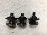
sundstrand mnt3.jpgsundstrand mnt1.jpgsundstrand mnt2.jpg

As you can see the main mounts have compressed with quite a variance and gave it quite a bit of room to give it the shakes. One of the mounting bolts is actually bent at the threaded portion. Knowing nothing of later 10ee's do they have a similar dampening system? I have a flat belt drive on the lathe and it did not track very well, this is probably why. The belt would also come off if I was doing too heavy of an interrupted cut. The one mount that doesn't have much evidence of being compressed measures .75" tall. I'm thinking maybe a tad larger would be fine since this is 75 years old. Any suggestions on the material to use. While I'm at it I'll make a new cross feed screw and nut too.

Thanks Z
 
Mine also has a flat belt. Too aggressive a cut will cause it to throw the belt. The belt that is on it has a little bit of flex, so I plan to try a belt with less flex to see if that helps. I found that the idler pulley tension needs to be high, and I keep the idler pulley angled forwards a slight bit.

t doesn't shake, so I can't help you there.
 
I ordered some 1.75" neoprene spring rubber this morning and actually got it this afternoon from McMaster Carr, helps when they are local. Got all the pieces cut on the band saw and hope to get it back together tomorrow and see if that gets rid of the shakes. There was quite a bit of movement in the sump base when I pried it up with a long screw driver. I thought about changing the flat belt with a serpentine, but just haven't gotten around to it. I'm also missing the idler and the belt rubbed the casting which I'm sure contributed to the situation.

A few questions for you: What diameter idler do you have and does it just mount on a T stud or is there a bracket that mounts it to the slot?
Thanks again Z
 
A few questions for you: What diameter idler do you have and does it just mount on a T stud or is there a bracket that mounts it to the slot?
Thanks again Z

The idler is the same diameter used by all 10EEs. I'm in Germany right now so I can't give the actual dia., so perhaps someone else will respond. It has a t-bolt and fits the slot on the back side of the belt. The Sundstrand machines have the flat ledge on the front side so it should be possible to fit an idler & bracket from a later 10EE in front.
 
Got the rubber mounts set and the base plate back in and decided to run the "power unit" before I slid it back into the lathe cavity. I had to run a temporary line to the motor as the whip isn't long enough with the assembly out. Had two leads reversed and started it with the wrong rotation. Found the vibration problem. Starting it in the opposite rotation broke the pulley on the input shaft of the Sundstrand pump free from its Rube Goldberg fix. At some point the key failed and the shaft keyway got messed up.

sundstrand input 1.jpgsundstrand inpur 2.jpg

As you can see the shaft is screwed up and the bore on the pulley is sloppy also.

Not quite sure what its going to take to remove that shaft and make a new one
R. Kepler was nice enough to send me a users manual back when I acquired the lathe, but it really doesn't give a breakdown of the assembly.
Thought about boring out the pulley and making a bushing to span the whole length of exposed input shaft as a temp measure.
 
I think I had a bit of "wishful thinking" about the rubber mounts being the problem. I'm also a bit apprehensive about pulling apart a 75 year old hydraulic motor that's unsupported. Whatever remedy I use in the long run I'm sure will be a lot better than what I'm left with. At least I'm finally getting around to making it useful again.
 
Meanwhile, do some research on the 'QD' mounts if you've not used them before.

My learning curve on QD mounts was abrupt, snapped a mower blade spindle shaft on the old "cub" hitting a stump. When I tried to pull the pulley off I broke the casting as I was pulling against the taper, doh!
 
Well I've decided to take the shaft out as the wear from the poor fitting pulley was at about .040 aside from the keyway being messed up. Been doing some research on welding it, mig, tig, spray. Any thoughts or experience? The diameter at this end is 3/4 and didn't know how much distortion would occur. Not quit sure if I can remove the wobble bearing too easily and probably wont for fear of breaking it.

sundstrand input shaft.jpg
 
I had the spindle motor on my mill chip the shaft right at the keyway and destroy itself there. Ate the key as well, but the gear it drives was good. I pulled the rotor out of the motor and set it up in my lathe with the steady rest holding the end bearing and dialed it in with as little runout as I could. Then pulled it out and tig welded the shaft adding material to be turned round again. Returned it to the lathe and turned it to the original diameter. I never used the original center that was in the rotor as I figured it may move during welding and the subsequent shrinking from cooling. Took it out and measured the runout and found it better than Baldor's original high end motor specs, half that actually. Handed it off to a friend to recut the keyway and reinstalled it. Worked great.

I've actually done this same thing 3 or 4 times now on other shafts and motor rotors. It has always worked well for me. The hardest thing for me on that first rotor was dialing in the steady rest, but I got it figured out. I'd never used one before.

Bob
 
I'd just skim it clean, then:

Bill

Turning it down seems like the logical starting point and then go from there. Figured I'd get all options on the table.
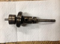
While inside the pistons on the input shaft will need cleaned up as their domes are pitted.
sundstrand pistons.jpgsundstrand piston.jpg

The mating face on the wobble bearing has a few blemishes but I'll have to live with it. The output shaft assembly looks very nice with no wear on the pistons or bearing face.
 
Turning it down seems like the logical starting point and then go from there. Figured I'd get all options on the table.
While inside the pistons on the input shaft will need cleaned up as their domes are pitted.
View attachment 136437View attachment 136438

The mating face on the wobble bearing has a few blemishes but I'll have to live with it. The output shaft assembly looks very nice with no wear on the pistons or bearing face.

Please take lots of photos that show the internal assembly. It will help the next person faced with a Sundstrand rebuild.
 
Turning it down seems like the logical starting point and then go from there. Figured I'd get all options on the table.
While inside the pistons on the input shaft will need cleaned up as their domes are pitted.
View attachment 136437View attachment 136438

The mating face on the wobble bearing has a few blemishes but I'll have to live with it. The output shaft assembly looks very nice with no wear on the pistons or bearing face.
I'm really looking forward to learning more about the Sundstrand, so I too hope that you'll post lots of photos of the innards.

Is it possible that the domes on the pistons are hardened steel balls that have been soldered (or whatever) the to pistons? If so, maybe replacing the balls is the way to go. Are they a common diameter?

Would you please have a look at the beast and see if you can find any patent numbers?

Cal
 
Hello and thanks so much for starting this thread.

I just purchased a 10EE with a Sundstrand drive. Your thread is most helpful as I will be heading down the same road. Mine was supposed to have been running when it was parked a decade or so back.

If I can be of any help as far as photos, etc. of the inside of my machine, please don't hesitate to ask and I will do anything a person with as little knowledge as I possess can.

Please keep the posts and photos coming.

Thank you.

Bob

I've moved my equipment to another location and thought it was time to set up my 10ee properly. Back wen I got it I found an open slot and left it on the skid till it found it's permanent resting place. Had some issues when I first fired it up with vibration and slowly started to work them out, bad belts, still on skid etc, but still had a little shake to it. Now mind you it wasn't consistent through the rpm range. Now that I moved it and got it off the skid HOLLY crap this thing shakes! My skid must have acted as a dampener. So I pulled the motor to check the bearings and they seemed fine. After looking things over I noticed some small rubber pads between the hydraulic sump and the base plate, then saw large rubber blocks under the base plate. Next everything came out and I'm hoping my trouble is just in the rubber mounts.

View attachment 135776View attachment 135777View attachment 135778

As you can see the main mounts have compressed with quite a variance and gave it quite a bit of room to give it the shakes. One of the mounting bolts is actually bent at the threaded portion. Knowing nothing of later 10ee's do they have a similar dampening system? I have a flat belt drive on the lathe and it did not track very well, this is probably why. The belt would also come off if I was doing too heavy of an interrupted cut. The one mount that doesn't have much evidence of being compressed measures .75" tall. I'm thinking maybe a tad larger would be fine since this is 75 years old. Any suggestions on the material to use. While I'm at it I'll make a new cross feed screw and nut too.

Thanks Z
 
What would have caused the domes to have become pitted? Impact? Corrosion?

Thanks

Bob

Turning it down seems like the logical starting point and then go from there. Figured I'd get all options on the table.
While inside the pistons on the input shaft will need cleaned up as their domes are pitted.
View attachment 136437View attachment 136438

The mating face on the wobble bearing has a few blemishes but I'll have to live with it. The output shaft assembly looks very nice with no wear on the pistons or bearing face.
 
Bill.

Interesting. Makes sense.

I wonder what mine look like?

Thank you.

Bob

I'd bet on electrolytic corrosion.

May sound strange in an oil-filled system, but EDM uses a dielectric oil, and we do have to 'ground' gasoline pump nozzles. All that churning generates an electric charge in a similar manner to pumping fuel or flowing hydrocarbons through a line.

Big factor?

No.. not at all. Many orders of magnitude slower than EDM.

However .. AFAIK the newest Sundstrand drive in a 10EE shipped about 75 years ago. Even a slow process has had lots of time to act, and the tips of the pistons would have been the warmest spots - working under the pressure of 'attempted deformation' and with a local film-shear that gave rise to higher disturbance up close and personal in the fluid than the general flow of pumping alone.

Bill
 
Just getting back to everyone, good to see there's plenty of help and interest available on the Sundstrand. I've taken quite a few photo's and plan on giving a better step by step process. The literature I received from R. Kepler years ago was a big help after I read it a few times and figured out what was where. It was vague and I had at least one good "oh fudge" moment.
It's going to be slow getting back though.

Z
 
I have since turned the shaft down to .6875 and will get a taper lock bushing. I have not found a matching 7" pulley for a C (7/8) belt. The pulley on the motor is variable pitch and is that type for tensioning purposes as the motor and drive are fixed in position. I may make a flange to accept the bushing and fit the existing pulley to it. There's been no problem in finding pulleys for smaller belt though.

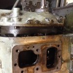
Here are a few pics of the tear down process.

sp1.jpg
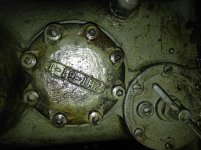
This is the makeup pump just above the filter screen. Remove the 8 bolts being careful in only removing the cap, leave the center spacer as it holds a roller bearing in place.
Hence my "Oh Fudge" moment.
sp2.jpg
Here is what you will find
sp3.jpg
Take the outer spacer off and catch the rollers that fall out and spin the cage and collect the rest.
Next pull the gear and key.
sp4.jpg
 
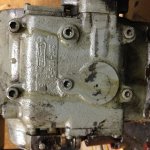
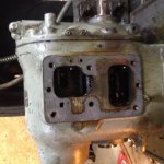
Next from the side
sp22.jpg
remove the six bolts holding the speed adjusting housing
sp20.jpgsp23.jpg
Once off I took a dead blow hammer and broke the rear housing loose.
sp25.jpg
Then you can hit the end of the output shaft with the dead blow along with the end of the input shaft at the makeup pump end
sp24.jpg
when the input shaft gets to the housing I used a 1/8" brass pipe nipple as a punch.
 
For some reason the pics are off 90 degrees and I can't rotate them, so have a few beers to compensate. Unfortunately I didn't take a pic of the end housing with both shafts in tact. I can always add that later when I reassemble.

Have more, but can't upload at the moment.
 
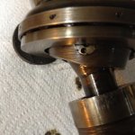
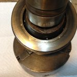
Here's a few of the wobble bearing
sp7a.jpg
I would have taken the bearing off but the face that the pistons ride on is in the way of removing the pivot pin. Not sure of how to separate it and don't want to break it. When I turned the end of the shaft down I just wrapped the bearing with tape to keep it from throwing things out of balance.
As you can see there are some blemishes on it which attributes to the piston wear.
sp6.jpgsp5.jpg
more of the pistons
sp13.jpg
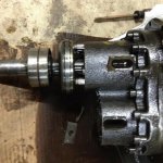
here's the output shaft
sp18.jpg
Unlike the input shaft the output shaft's pistons ride against a radius.


Back
Top