What's new
What's new

What are the last 10 projects you did on or for your 10EE

rimcanyon

Diamond
Joined
Sep 28, 2002
Location
Salinas, CA USA
All the trouble-shooting posts are interesting but a change is nice once in a while. How about a new subject for those of you actually using your lathes (or fixing them up):

what were the last 10 projects you used your 10EE for, or were for your 10EE?

I'll start, starting with most recent:

1. extension for 6" drain grate to raise it above a new concrete slab out of 6" aluminum tubing.

2. 1/4-28 lock screws for Delta 6" jointer cutter head knives.

3. turned ornamental heads on standard 1/2" bolts for bed posts.

4. installed Mitutoyo quill-type DRO on saddle for cross slide.

5. designed and fit metric gears to round dial lathe and used it to cut threads in collets for Deckel high speed head.

6. a set of 12 collets to fit Harig air spindle.

7. hinges for 100 pound ornamental iron gates for patio.

8. a replacement bearing clamp for a 4" super spacer.

9. holder for 25mm cutoff tool to fit BXA toolpost.

10. replacement delrin wheel and axle for house vacuum.

Nothing terribly challenging, although getting the collets accurate to half a thousandth was time-consuming & a few ended up in the hydraulic press bushing collection ;<) A lot of these could have been purchased, but at much greater cost in time and aggrevation. There is just something very satisfying about being able to make or repair anything you are likely to need.

-Dave
 
Ok, heres a few: Sorry only four that I can think of. :(
1) repaired both EE apron clutch rods, by cutting the scored rod off and threading the yokes to accept a new rod. Then, threading the new rods on the ends w/ setscrew, to accept the new outboard shaft, doing this instead of installing a taper pin. At least its now sorta adjustable.
2) Rebuilt apron oil pump, using good hardly used pump in place of fully worn out original and making a new pump outer shaft bush.
3) installed new copper oil lines in carriage/apron, with new metering valves. fun job.
4) scraped in threading half nuts into their ways, and applying turcite to the bottom of the half-nut ways to bring them up to proper clearance with the bolt-on guides, that also needed to be scraped flat. Luckily, the hardly used round dial half-nuts that I procured, where just alittle bit wider than the ways, but alittle thinner.
 
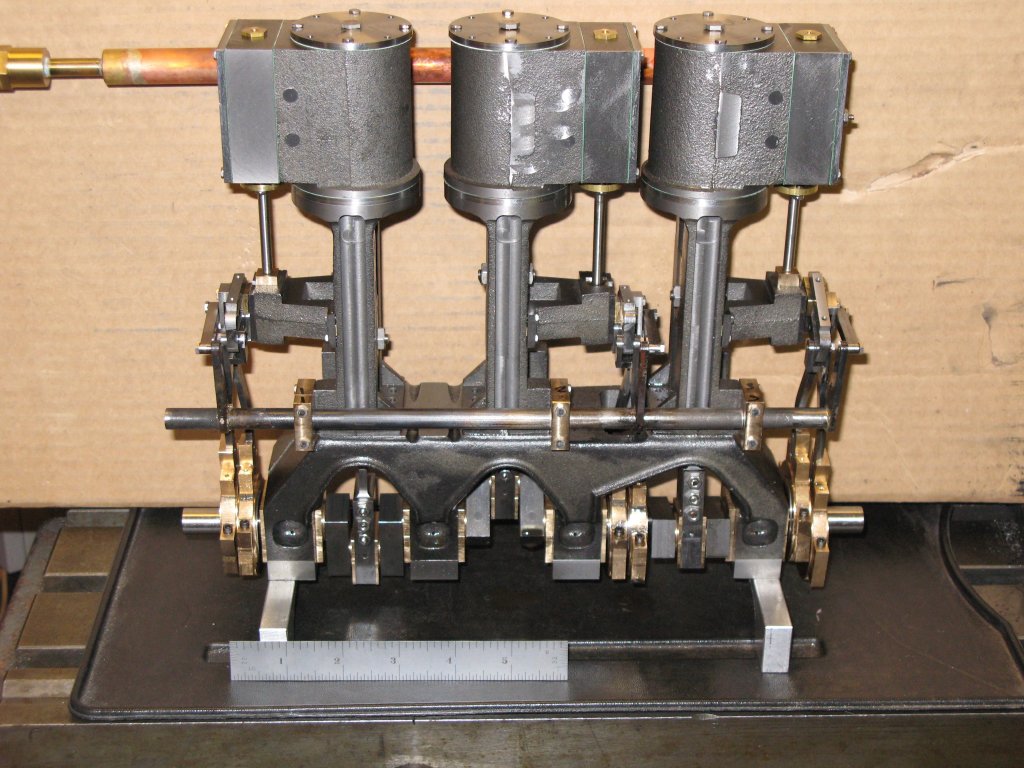
Since I turn on the lathe almost daily I can't recall specific projects. I did "finish" this:

shay_engine.jpg


It's a 3 cylinder steam engine for a 1/8 scale Shay 3 truck Class C. It's not finished, it's just in the "does all this stuff work together" assembly and is missing about 2/3 of the assembly screws and all paint and polish. The eccentric sleeves have to be finish filed, they're still in the original as-cast dimensions for the most part.

It's on a sort-of hold until the weekend, I have to make and fit new valve sleeve guides as the old ones had to be shimmed .010" to .014" out to make them work. I'll probably remake the snifter valves, there's very little meat under the thread and the last one took about 4 tries before one didn't twist apart in assembly.
 
"What is a Shay 3 truck?"

Shay, a type and brand of geared locomotive formerly made under license by Lima Locomotive Works, Lima, Ohio.

In a Shay, the engine is on the side of the boiler, and each driving axle is geared from shafting suspended below the engine, not driven by conventional side rods and cranks.

Two truck Shay: two driving trucks, both under the engine.

Three truck Shay: three driving trucks, two under the engine, one under the tender.

Shays are most often found in logging operations, where the grades may be too extreme for a conventional locomotive.

A variation of the Shay concept is the so-called "West Coast Shay".

One is still operational here in Santa Cruz.
 
As Peter mentioned the Shay was the first geared locomotove. Most locomotives were designed for relatively smooth tracks with low grades and high speed operation, the Shay was designed for rougher tracks, higher grades and lower speed operation - typical operation for mining and lumber operation. Think of the Shay as the 12-wheel drive locomotive.

Here's a link to a shot of the class of Shay I'm modeling:

http://www.shaylocomotives.com/surviving/3233surv.jpg
 
Russ:

I didn't know that they made such a beast.

Wow I thought that some of the old tractors I've seen run made a lot of smoke. They didn't even start that Shay, looks like they're burning tires for fuel.

If an EPA inspector saw he surly have a heart attack


Russ keep up the good work and keep the pictures coming.

Hal
 
Dave, Do you have a photo of the mounting of the Mitutoyo quill-type DRO on saddle for cross slide?

I for one, and maybe others too, would benefit from seeing your mounting.

What am I doing.....taking tailstock off, reshiming, mounting, measuring, taking tailstock off, reshiming, mounting, measuring. What fun, but I am real close to almost perfect, well at least worlds better.

Michael
 
Here are a couple of pictures of the Mitutoyo quill DRO. The bracket is held to the saddle with a 1/4-20 cap screw on each side, and the DRO head is attached to the cross slide with a pair of 10-32 cap screws. The bracket is tight against the way wipe cover on the left, and it is at the same height as the way wipe cover on the tailstock, so if the tailstock hits the bracket it stays put. It reads in radius not diameter, but that is easy to remember.

-Dave

quill_dro_1.JPG


quill_dro_2.JPG
 
Made a follow rest for the 10EE from a South bend (?) follow rest, ( since the real thing is so hard to come by)
I also made 3 CRS feet for the lathe which you can adjust the height from above ( not crouching under this 3,500 lbs hunk of iron)
 
1. Made 30 control arm inserts(1"oal,.867 od,3/8 nf id.). These weld into the end of tubular control arms, and accept hiem joints.
2. Made 60 pushrod inserts.(1"oal,.561 od,5/16 nf id.[1/2 of the 30 are left hand thread])
3. Made 15 outer arm bungs.(1"od, tapped 5/8-18 for 1/2 of 3 1/4" oal, remaining id is .880)
4. Made 30 control arm struts,useing the boring bar holder on compound to cope 1" tubing with a 1" roughing mill mounted in chuck.
5. Made spacers for mounting 10" grinding wheels.
Out of time for now, I'll finnish up soon. Great idea Rim, love this post. Thanks
 
The last ten are the same as the first ten.
1. Remove Wiad and decide to install VFD.
2. Replace bent ELSR rod, find the orginal rod
was hand drilledfor taper pin, not on center.
3. Remove ElSR box disassemble and find old lube is like dried toothpaste in bearings, frozen,bearing spinning on shaft.
4. Find out the key that drives the ELSR control rod from the apron is $125, make new one.
5. Have my bike detailer clean the lathe, (very easy) for me, not him.
6. Check microswitches in ELSR find one bad switch, spend an hour looking for source of switches. Grangers $8.
7. Call a buddy in auto parts Bis. for drive belt to run the power feed gearbox, polygroove 37 7/16 x1.5 $20
8. Layout wiring for VFD installation.
9. Set back gear cover on mill, use DRO to layout pattern for drilling mounting hole in adapter plate.
10. Wait for various parts to arrive, order more, sort Wiad parts for new owners, write this post.

my wheels don't slow me down
&.
 
There is a running Shay locomotive in Cass, West Virginia, near Wintergreen ski resort. Very interesting old sawmill town. You can take a ride on the train along the old logging route.
 
Still dont have my EEs set up. I had to make a quick shaft for a Hobart mixer on the L&S Powerturn.
The shaft only 1" dia and 8" length with two bearing surfaces and a short thread on the end was a bit of a chore. Held great tolerance though, would have taken half the time on the nimble EE.
 
Dave:

In the first photo showing your DRO your Trav-A-Dial can also be seen.
What does the knob below the bezel do. Is that the tilt adjustment to fine tune your Trav-A-Dial?

Hal
 
The knob tightens a clamp that locks the travadial in place on the dovetailed bracket. It also provides a way to adjust the position of the travadial (along with the force holding the travadial against the side of the bed, so that the wheel won't slip).

The tilt adjustment uses a pair of cap screws from the bottom, and the angle adjustment uses a pair of setscrews from the side.

The mounting bracket is from a larger Monarch lathe, probably a CK. I had to adapt it to fit the 10EE saddle height. It used to have two mounting holes; now it uses the one along with a shoulder milled on the bottom that registers against the block in the center.
 
Hi all,

As usual, life has been happening to me, but I am finally getting things back together. Just started back to work on the EE 30", and does it feel good to have some fun again or what? Here's the last ten things I've done, most of them this week.


1. Took the sawzall to the sheet metal that’s in the way in the back transformer compartment. Now I can remove the whole shroud by taking out 4 screws.

2. Replaced the Gen. Dynamics motor with a GE one. Tapped the front right leg (back right side looking into the motor compartment) and drilled out the tapped hole in the motor plate. Once I get the EE going how I want it, I will turn the comutator on the Dynamics motor and switch back. It will be a snap not having to deal with that one bolt from above.

3. Took off saddle and apron. Replaced all oil lines and metering valves. Re-did pump. Filled cross slide channel with bondo (like a idiot). One port wasn’t getting oil. Dug out bondo, replaced line. This time squirted oil with pump oiler at the big junction thing in the saddle. Still didn’t work. Removed line and valve again . Brand new metering valve would not pass oil. Put in new one (size OH? from previous owner). Works fine. Cleaned channel with Sprayon layout fluid remover and packed with Mega Black. Much better than bondo.

4. Replaced sharp gears in apron with like new ones from parts machine. Swapped cast iron half nut with brass one from parts machine – more on this in a separate thread.

5. Took out gearbox – replaced two gears. Installed new bearings (water coolent used on manufacturing lathe) both head and tail, lead screw and feed rod.

6. Split lead screw nut in compound, drilled and tapped and installed spreader screws (jack screws?) to take out backlash. Shimmed and replaced bearings.

7. Replaced bearings in cross slide, removed pin and dial tightening lever, ground a little off the screw end of lever and replaced pin. Now it works right. Before the pin was in exactly the wrong place and the dial would not tighten enough. On the other side of the pin, it was too tight in the free wheel position.

8. Milled the top ¾ of metal off the long tongue thing in the cross slide that the taper attachment hooks too. Now the cover plate that goes under the compound will bolt down on top of the tongue thing (where I milled the top off) to keep chips out of the channel that the lead screw runs in.

9. Checked the tailstock which is 5 or 6 thousandths low after bed grinding. Ram moves toward front when locked half a tenth. No droop and really parallel to the bed. Pulled it apart, cleaned out blocked oil port, ordered bearing and shim stock which will be here about noon today.

10. Took a 3 1/2” cut on 7/8 stock up by the headstock in a 2J collet. Had a taper of 0.0003 total in 3”.

So it’s getting there. The longest problem to figure out were multiple electronic and motor problems. Harry solved the final one of those which was brush timing on the second motor. The electronics have been working good for a long time. I just haven’t had a chance until this week to get back on the remaining mechanical stuff.

Regards,
JimC
 
JimC,
how about some pictures?

I'm having trouble picturing a few of those projects, like the "tongue thing" modification, the split compound nut.

What year is the 30" and the parts lathe - the cast iron vs. brass half nut difference is something I was unaware of.

-Dave
 
Dave,

I broke my camera and won’t be able to post pictures until I can get another one.

The mfg. lathe is a 1967 and the parts lathe is a square dial wiad that I think is 1958. I looked for a date but couldn’t find one.

The tongue thing is that bar about 16” x 5/16th x about 2” with the slot in the middle that sits over the chanel where the lead screw is on its own ledge. The cover plate goes over the end of that chanel and sits in its own ledge and covers up the lead screw and bearings when the compound is run way back toward the back of the lathe.

So I just machined off the top part of the bar and now the cover plate will sit down in its spot, and the remaining part of the bar where I took the top off can go underneath that plate.

What I did with the compound lead screw nut was stand it on end in the bridgeport and drill four holes in one end about ¼” deeper than half way to the other end, and then tapped them for 6-32 set screws. Then I put a thin saw in the Bpt. and cut through the middle of the nut to about half way down the tapped boss that goes into a hole in the compound base with typical Monarch tolerances.

Then I turned the threads off the ends of 4 long 6/32 set screws and ran them into the tapped holes in the end of the nut. When they bottom out in the holes on the other side of the saw cut, they start pushing the nut apart and taking out a lot of the backlash.

The lead screw nut on the 30” was the cast iron one. There were two reasons I changed. One was that there was no height adjustment in the cast one and I would have had to of machined the bolt holes oblong one the cast one. The ways were ground down 10 thousandths and I couldn’t get the half nut to keep from pushing the lead screw down when engaging. When I tested it before I started messing with everything, the cast one didn’t move the lead screw. But with the brass ones I was able to get adjustment so that wouldn’t happen.

I cut a keyway in a short piece of round stock, and followed the feed bar out of the apron with that short chunk to keep everything aligned. then I put the casting back on the tailstock end with the lead screw in it and ran the saddle down as far as I could get it toward the tail stock. With the feed bar removed, I was able to tighten up the half nut bolts (then test them) toward the middle of the lathe.

The other reason I changed them is that I was getting horrible vibration with the other one in there, and was hoping the brass one would do better. But I got to get home now.

Regards,

Jimc


Back
Top