clayton
Aluminum
- Joined
- Aug 19, 2011
- Location
- Houston Texas
I’m new to lathe programming. I am trying to program a pretty simple radius on a 1.0x.625 diameter spacer. The radius is 1.6” and starts .1 in from face and ends .1 was back of part.
I have searched YouTube and googled, but I don’t find anything that seems to be relevant to this control. There is a lot of talk programming with the Radius method. But as I have read you have more control with I and K.

I’m not understanding how to figure the math for G2/G3’s, and using I and K.
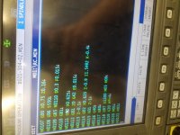
I tried to copy what my cam software spits out and only use the G2 line. It almost works as expected trying to drop that line into my lap cycle. But it comes up and goes back for the .1 off the back of the face and it’s undersize .005 as shown in the image below.

I told my cam software to output G42 but do not calculate tool compensation.
Below is the complete post from the cam software, but I was only using the G2 line.
The turning segment of code in my program within the lap cycle shown below

Again, I’m a complete noob with programming at the control on a lathe. And I’ve never uploaded a post into my lathe from any cam software. I’ve been trying to learn how to program by hand. But I lack experience.
Thank you for any help I appreciate it.
I have searched YouTube and googled, but I don’t find anything that seems to be relevant to this control. There is a lot of talk programming with the Radius method. But as I have read you have more control with I and K.
I’m not understanding how to figure the math for G2/G3’s, and using I and K.
I tried to copy what my cam software spits out and only use the G2 line. It almost works as expected trying to drop that line into my lap cycle. But it comes up and goes back for the .1 off the back of the face and it’s undersize .005 as shown in the image below.
I told my cam software to output G42 but do not calculate tool compensation.
Below is the complete post from the cam software, but I was only using the G2 line.
Code:
 %
(1001.MIN)
G50 S6000
G0 X400.
G0 Z400.

(PROFILE2)
T000101
M8
G95
G97 S770 M3 M41
G0 X1.4876 Z0.1969
G50 S5000
G96 S300 M3 M41
G0 Z0.0254
X0.7557
G1 X0.6757 F0.005
G18
G1 G42 X0.5626 Z-0.0312
Z-0.1312
G90 G2 Z-0.9312 I1.5492 K-0.4
G1 Z-1.0312
G40 X0.7226
G0 X1.4876
Z0.1969
G97 S770 M3 M41

M9
G0 X400. Z400.
M2
%
The turning segment of code in my program within the lap cycle shown below
Again, I’m a complete noob with programming at the control on a lathe. And I’ve never uploaded a post into my lathe from any cam software. I’ve been trying to learn how to program by hand. But I lack experience.
Thank you for any help I appreciate it.