What's new
What's new

Lathe won't start after move

Joined
Mar 10, 2021
Location
Ireland
Hello,

I've a SAG12 that I recently purchased. I'm new to machining and was lucky to pick up a the lathe for 1k. I tested everything at the buyers shop, it all worked fine no problem. It was plugged into wall threephase 380v.

I brought it to my shop and it sat for two months while I got a digital phase converter online. I initially wired it upstream of the whole lathe, I could here humming but nothing worked. I wired it directly to the motor and the motor spins fine, but I can't seem to get the chuck to spin/clutches to engage. I've been trying to figure out the electronics on my own, but I am honestly stuck at this point.

I've attached the wiring schematic. I'm trying to figure out how to test if the currect voltage is coming out of the transformer. From the diagram where should I see 24volts? Should it read 24volts on the "7" or "8" on the bottom running to the joystick or clutches? any advice on what to check or how to troubleshoot would be greatly appreciated.

We're in lockdown here in Ireland for another two months so would be great to learn a bit of machining while stuck in the house. Thanks for any replies and your time!
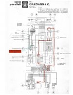
 

Attachments

  • sag12 schematic vfd change .jpg
    sag12 schematic vfd change .jpg
    89.7 KB · Views: 64
Dinky,

I don't know much about electrical stuff....

I have a Sag 12, so I turned on the main switch (F) and checked the voltage at '7' as you requested. It was 47 VDC. This wire actually goes to the pressure switch on the transmission, but I believe the same voltage is used for the clutches.

One of this forums members is optoeng (Paul). He has a Sag 12 but doesn't have three phase power, so he fitted a VFD to power the motor, pretty much what you are trying to do (I think).

Here is what he wrote:

I made some circuit changes to get my lathe running. 3-phase power is unavailable here, so I installed a VFD operating at 60 Hz to power the motor, and I wired the control circuitry directly to one-phase 220VAC. The VFD gets triggered by one of the relay contacts formerly used to drive the motor, so that the oil pressure switch and the motor ON and OFF switches function normally. Of course, the joystick also functions normally.

I suggest you send him a Private Message and perhaps he will explain the details?

Note, he is in North America, so voltages and motor terminal configurations are probably different than yours.


BTW, he wrote a good description of how the Sag 12 control circuitry works. See post #7 on this thread:

GRAZIANO SAG 12 -24 VOLTS FROM UNIT

--------

Getting back to my Sag 12 which runs on 415 volts three supply - the three phase supply is connected at 'R', 'S' & 'T'.

--------

The original transformer on my lathe has the following markings: Primary (input) 415,
Secondary (outputs) 24 & 30. I checked with a multimeter and it measures 402 volts in and 25.5 VAC and 29 VAC out.

I have seen a photo of a Sag 12 transformer on a USA Sag 12 (Texas Turnado) which had options for 220 or 400 volt primary, whereas mine only has the 415 volt option.

If your transformer is like mine, I am guessing you will need to change it to one that works from your 220? volt supply. My guess is your transformer will be like mine, not the North American version.

The late Texas Turnado also used a VFD to supply his Sag 12 from single phase. He ran into some problems with the VFD tripping out when changing gear, but he solved it with a bigger VFD. Let me know if you want the details.


To other readers, I see there are related threads on the VFD forum:

https://www.practicalmachinist.com/...rs-and-vfd/where-wire-vfd-388689/#post3731024

SAG 12 VFD Conversion
 
Peter,

Thanks so much for testing that and for those links, an unbelievable help.

I've a new multimeter in the mail that can test that range of DC current so will be able to get on with troubleshooting when that arrives. Your right in that I'm trying to essentially run the lathe off a VFD. They sell these things they market as 'digital phase converters' that, when oversized, can supposedly can be wired upstream of machines life rotary phase converters and not directly to the motor. It didn't work upstream but does work when directly on the motor, so decided to just go ahead run the dc components off 220v single phase as i have to troubleshoot the whole setup anyway.

i'll be bugging Paul here once I get my questions in order. This forum is a lifesaver!

Jonah
 
I don't know if the transformer has a 220 volt option. It doesn't have any writing or markings on it so it's hard to know. I does have a a bunch of wires that aren't used and it appears to be the original so i imagine it was designed to take 220 as well as 380 as the rest of the machine is designed to do that.

I finally got a decent multimeter and have made some progress. I know that the 380v three phase is making it to the motor remote control switch (numbers 1 3 5 ) and it's not coming out the other side. For some reason if i push control switch (I believe its also called a contactor) in manually while the power is on it shuts off the digital phase converter with an error that says "incorrect voltage." The same also happens if i press the stop botton on the lathe, it causes the digital phase converter to turn off with the same error. Nothing happens when i press the start button. The man who sold me the digital phase converter said he thinks there's a fault or short somewhere.

I checked the transformer and bridge rectifier and i'm getting a full 30v out of the rectifier.

The only other thing that i can think might be an issue is "G" in the schematic. It's labelled as the low current cutoff fuse. I not sure which wire this is. There is unfortunately a lone wire hanging out of the transformer (not power in or the two out, a 5th wire) -- when i first opened the unit after the move it has a small bit of red tape on it's end, so may connect to something or may not..

I also can't figure out what is lowercase "a" on the motor or electrocpump control contactor/switchl any thoughts on that would be greatly appreciated.

I'm maintaining the faith that if i just poke and prod long enough something will work, we're in total lockdown for another two months in ireland so no electricians can come work on it.
 
I know that the 380v three phase is making it to the motor remote control switch (numbers 1 3 5 ) and it's not coming out the other side.

Dinky,

Can you clarify something, are you getting 380 volts or 220 volts output from your phase convertor? If your phase convertor has 220 volt input, surely it has 220 volt output too?

That is why I asked about the transformer, if you are running on 220 volts, then I would guess you have to change the transformer primary tapping's from 380 to 220 (if it allows you to, mine doesn't).

You mentioned there were no markings on your transformer. On my transformer there is a piece of black cardboard behind the terminal block which has the voltages stamped on it The numbers identify the voltage of each terminal or pair of terminals.

I have attached a photo, the black cardboard is circled in yellow. You can't see the numbers in the photo, but they are there.

But yours could well be different, mine is different to the photo in the manual and different to the USA ones I have seen on PM.

Sag 12 transformer 01.jpg

Regarding 'G', I guess that is one of the big round ceramic fuses. The photo in my manual shows the fuse in a different location to my lathe. Can you trace the wire from the fuse back to the transformer? It looks (on schematic) like it goes to a 24 volt tapping, probably 24VAC.

From what I have read, the 24VAC secondary winding on the transformer is used to power the contactors, i.e. when you push the motor 'on' button, the 24VAC powers the solenoid which does the high voltage switching.

(The 32VAC secondary is rectified to 45VDC for the transmission clutch coils).

Here are a few photos of my cabinet. It is a bit rusty in places, it had mice living in it when in storage...

BTW, there is a non-original black fuse holder near the bottom of my cabinet, it was fitted for a single phase 230 volt outlet (for a work light). I think the cable ducting looks non-original too, and maybe the long terminal block at the bottom of the cabinet.

Sag 12 cabinet 04.jpg Sag 12 cabinet 03.jpg Sag 12 cabinet 01.jpg Sag 12 cabinet 02.jpg
 
Dinky -

Just for clarity, is your VFD one of those that have been 'modified' by a UK supplier so that it takes an input of 230V AC and gives you 415C AC (or thereabouts)output?
 
Heya,

Again thanks so much for taking the time to reply. The 'digital phase converter' is essentially a three phase producing vfd that also steps up from 220v to 380v. I understand (well think i do from reading online) that VFD are usually best hooked to the motor directly, the sparks who sold me this machine has wired a load of them upstream of lathes and ran the whole machine off the regular start buttons, not ideal but works. So i went with this hoping i wouldn't have to mess with the electrics too much as it's not my strong point (or favorite point). But i'm half way there now figuring out what each component does so I'll keep at it.

The only thing that is keeping me from just running the phase converter straight to the motor is that there aren't marking on the transformer that show how to rewire it for 220v instead of 380v. It does appear to have the capability as it has four unused wires, now which one is which is anyones guess (or maybe there's a common coloring for 220v input to a transformer of this type?)

I'm still trying to find why the contactor isn't activating when i push the start button. Neither the pump nor the spindle motor activate so it has to be something with the entire control circuit. I think that eliminates the timer as as the issue. It must be the fifth wire, I think I've identified what the other four are, but I'm going to go back tonight and have another go at it so I'll post again if I figure anything else out.IMG_20210328_191006.jpgIMG_20210328_184202.jpgIMG_20210328_184333.jpgIMG_20210328_190932.jpg
 
Jonah,
OK, thanks for that clarification re. 380 volts from your converter.

If (as I think you are saying) the converter seller reckons you can use it as if it were a normal 3 phase 380 volt power supply (i.e. "upstream"), have you got the 3 phases connected to the 'R' 'S' & 'T' terminals? I got the impression earlier that you had connected them somewhere else.

------------------------

BTW, did you say in another thread that you had re-configured the motor for 220 volts? (When you were testing the earlier VFD). If so, the motor will not be happy getting 380 volts, in fact it will burn out the motor within a few minutes. (Apologies if I am pointing out the obvious).

----------------------------------------

Another thought - you mention a 380 volt supply. Wikipedia reckons Ireland uses 415 volts. Not sure if that matters....

-------------------------------------------

If you decide to go with what I think is the usual VFD route and switch the converter on the input side and wire the outputs direct to the motor, could you not take a 380 volt feed from the converter to power the transformer? Then you wouldn't need to change the transformer.

Eventually you could then do what I think Paul (opoteng) did and reconfigure the wiring so the original motor push button turns on the VFD. I think Paul used one set of contacts of the original motor contactor to do this (presumably switching the single phase supply to his VFD).


I am out of my depth on this. I have used VFD's quite a lot, but straightforward stuff e.g. changing motor terminal configuration between high and low voltage, setting VFD parameters and the like.

I reckon some of the guys on the VFD forum could sort your problems out, but you would first have to explain the unusual Sag 12 motor, transmission and control set-up.
 
Dinky O'Sullivan said:
I don't know if the transformer has a 220 volt option. It doesn't have any writing or markings on it so it's hard to know. I does have a a bunch of wires that aren't used and it appears to be the original so i imagine it was designed to take 220 as well as 380 as the rest of the machine is designed to do that.

That toroidal transformer, I would certainly say, is in no way original. You mention a sparky sold the machine...I'd expect he'd be a likely culprit.
 
If (as I think you are saying) the converter seller reckons you can use it as if it were a normal 3 phase 380 volt power supply (i.e. "upstream"), have you got the 3 phases connected to the 'R' 'S' & 'T' terminals? I got the impression earlier that you had connected them somewhere else.

------------------------

I had it connected direct to the motor to test if it worked - and ran smoothly, but obviously no clutch engagement so unable to use the machine.


BTW, did you say in another thread that you had re-configured the motor for 220 volts? (When you were testing the earlier VFD). If so, the motor will not be happy getting 380 volts, in fact it will burn out the motor within a few minutes. (Apologies if I am pointing out the obvious).

----------------------------------------

I did recofigure for 220 for a smaller vfd i had to test if the motor was bad, and and then went back to 380v when the larger phase converter arrived. (sorry I'm learning as i go so my posts are a but all over the place)


Another thought - you mention a 380 volt supply. Wikipedia reckons Ireland uses 415 volts. Not sure if that matters....

I think the motor is original, so would be 380 from italy -- it seemed to run fine when connected direct to motor.


-------------------------------------------

If you decide to go with what I think is the usual VFD route and switch the converter on the input side and wire the outputs direct to the motor, could you not take a 380 volt feed from the converter to power the transformer? Then you wouldn't need to change the transformer.

Now that you mention it I think this is what i'm going to do. I can basically wire direct to motor, and then tap power off that line to run the transformer.


Eventually you could then do what I think Paul (opoteng) did and reconfigure the wiring so the original motor push button turns on the VFD. I think Paul used one set of contacts of the original motor contactor to do this (presumably switching the single phase supply to his VFD).

I remember reading that opotend did that and thinking it wasn't something i'd be able to achieve - three weeks of research and poking and prodding later and it seems fairly easy to do


I am out of my depth on this. I have used VFD's quite a lot, but straightforward stuff e.g. changing motor terminal configuration between high and low voltage, setting VFD parameters and the like.

I reckon some of the guys on the VFD forum could sort your problems out, but you would first have to explain the unusual Sag 12 motor, transmission and control set-up.

I think at this point i just need to figure out why the contactors aren't getting 24v ac. I didn't realize that they shoudl be running of ac and not dc (had never even thought 24v would ever be AC before) -- i'm confident it's not the timer, the transformer is working as well as the bridge rectifier, so basically thanks to all your helps I know where the problem.. Now i just need to find the little connection that's gone rusty of the wire that's come loose. I'll be at it again tomorrow, thanks so much for all your time.
 
That toroidal transformer, I would certainly say, is in no way original. You mention a sparky sold the machine...I'd expect he'd be a likely culprit.


The sparky sold me the phase converter, a guy who had broken his skull in a forklift accident and wasn't allowed to be near electric motors anymore sold me the lathe :) That's good to know it's not original. Does anyone know the specs for the transformer in case it needs to be replaced at some point?
 
The sparky sold me the phase converter, a guy who had broken his skull in a forklift accident and wasn't allowed to be near electric motors anymore sold me the lathe :) That's good to know it's not original. Does anyone know the specs for the transformer in case it needs to be replaced at some point?

Sounds unpleasant! No idea about VFDs, or any good with electrics, would think tappings should be the same as shown in post #1 if running conventionally, although I can't make out the last voltage...32v??

The transformer here has the same black backing with the input voltage as Peter's. Not a 12.....the outputs had varnished cloth tape with voltages written on them, in my case, 38, 20, 30 and 24v.


Back
Top