What's new
What's new

Schaublin 13 electrical questions

JorisKE

Plastic
Joined
Apr 5, 2021
Hi all

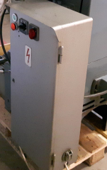
i recently found a schaublin 13 and got it. Now someone had been messing around in the electrical cabinet.
i have 3 contactors, i suppose 1 for the main motor; 1 for the rapid and one for the coolant pump?
or is this wrong? Because don't i need 2 contactors for left and right?
system works on 3 phase 380V and i have 380 V + N + E.

can someone provide me a picture of the inside of his original cabinet? or even better a wiring scheme?

Because it should just be a left-right motor scheme + rapid?

it is the last type from 1978.

big thank you in advance
 
Hi,


Why don't you start by sharing the wealth and show us a picture of the machine and perhaps a picture of the 3 contractors you speak of.

This way, everyone is on the same page, we all get to look at a great machine, and you improve your chances of someone having and sharing the information you need.

You see, we are simple people here, we like to look at Swiss machinery! :-)

Or, in case anyone feels misrepresented, with my statement, let me rephrase...

I am a simple guy, I like to look at Swiss machinery.

Good luck

Jacques

Sent from my SM-G998U1 using Tapatalk
 
U ask. Ik try to deliver. Spagettio
ab6773e5b1b20b5b0d7a4c60d648ddf0.jpg
4179dd687848bcd0f41a6b18db145178.jpg
e7f8ca59056e2bd87edc41ddcf3b1df9.jpg
04d8d576474aba6d7284016222bb477d.jpg
841fe2fbf35678ee7df891b93c424b88.jpg
e0f605166d680d1c3bfdb88ccad727d8.jpg
9339952df7402d72cd3cc7fd4ef074ee.jpg
adb9b79c8431510a4d30fef0c9a970b4.jpg
6f6da3b442bb7a8d7ef2b961e20f2216.jpg


Verstuurd vanaf mijn ONEPLUS A6013 met Tapatalk
 
ok so i had some spare time and this got me thinking

i used contactor 1 for the motor left turning and contactor 2 for right turning. There is no mechanical interlock it seems?
this should be the diagram

motorschakeling.jpg

i will be using the third for the rapid.

A lot of things seems to be redundant, i can replace 2 contactors by a motor starter with reverse.
i am thinking about replacing it by this: LZ2H6X5FU - Reversing Starter TeSys H 3kW-400V control 110-230VAC | Schneider Electric Global


now the only question i have is the switch with four positions. Does anyone has a scheme of that one? i tried measuring it out, but i get very strange results. i am thinking this switch is broken.
 

Attachments

  • schakeling motor.jpg
    schakeling motor.jpg
    19.8 KB · Views: 38
Wondering what is that mistery dead-body mark that the police left on the second floor, right side. Mine's have it too. Probably that big multi-voltage transformer was originally there. I have a few more previous owner "tuning" on this machine. Some wires are leading to nowhere, a fuse added.. very madmax style.
20230627_225802602_iOS.jpg
In the background, same dead body mark that the police did when the piece was killed.

Last picture shows my misterious device, which I hadn't had the time to think about it yet. Looks like a wi-fi router from the 70's! Who knows how much ahead of their time they were... but I believe it's just some contactor that does some contact contacting things.
20230627_225006241_iOS.jpg

Remembered to ask: what is the plug type of the coolant pump that goes into that rear outer socket? My coolant pump (non-original motor) doesn't have the plug and it would be nice to find a fitting replacement.
 

Attachments

  • 20230627_225802602_iOS.jpg
    20230627_225802602_iOS.jpg
    2.1 MB · Views: 0
  • 20230627_225006241_iOS.jpg
    20230627_225006241_iOS.jpg
    1.5 MB · Views: 0
This is the connector plug, does anyone know that is it's specification?
1688090744612.png1688090771142.png
It goes into that outlet with closing port in the rear of the electrical cabinet:
1688090836574.png
 
Hello Miannini,
I have an original electric diagram for a Schaublin 13, and also an electric diagram with all the electric components changed. You can find them below.
I hope it helps you.
 

Attachments

  • Schaublin 13 original electric diagram.pdf
    2.4 MB · Views: 18
  • Schaublin 13 Nr. 283151.pdf
    1.1 MB · Views: 13
  • Schaublin 13 original electric diagram.pdf
    2.4 MB · Views: 14
Thanks for the diagrams!
Last Monday I had a electrical engineer friend who helped me out.
The mistery dead body was transformer for the 6v panel lamps, which is missing (as is the case of most machines I ever seen), hence the mods on the diagram. I’m not going to use it anyway, so just a bit of tidying those ugly connections.
The panel was in 220v-3ph, utilizing two phases to get 220, so we linked it to a single 220v phase and the neutral (as I have residual difference disjunctor on my main power).
After that, all was a matter of tracing who did what and whatever needed to be rewired to 380v-3ph, such as Motors, big transformer (for electrical motor brake).
Mistery box is a contact box, no need to re-switch there.
In this older machines, the panel is 220 AC. I could have changed it to 24v DC, but only thought of that after the end of this re-wiring. Will have to wait for next time.
Answering the first question of this topic: there one contactor for each motor. Reverse is done in the switches, not using two separated contactors..
 
Ok nice to find these diagrams.
now rewiring it. never knew there was a brake function.
So basicly it has an on and off switch. A emergency stop. And the feed is changed by the lever.
And then the second motor is the rapid one.

I do not have the original coolant pump so think i am gonna weld a aluminium box and fit a coolant pump in there and just use 1 fase 230V like we have here in Belgium.

Still need to wire some things so will show the end product when it finally runs.
 
The motor brake function uses a bunch of diodes in a closed circuit, a transformer at 80v and two phases, plus a heat sink. It works by powering these two phases against rotation, electrically braking the motor. Mine’s probably not working, as it coasts to a stop. I believe it should stop the motor more quickly.
Basically, it’s a main switch, which cuts the three phases. The. There’s the rotation selector (CW or CCW), which also can select to power the coolant pump. Then there are two start and two stops, one on each side of the machine. There’s no locking emergency button. All panel is wired at 220v. Be aware that 220 3ph mains uses a different scheme of panel (maybe it uses 2 phases) wiring than if wired at 380v 3ph, which uses only a single phase. Those small power connectors are for 6v DC, which nowadays is useless and most transformers are missing from these machines.
I should have renewed all controls to 24v DC and installed an emergency locking switch (mushroom button). Someday I’m going to revise the motor brake circuit, perhaps linking it to a mushroom button, then maybe I’ll redo and update all controls to 24v DC (safer).
Feed speed is set on the rear of the machine, gets its power from main motor, regardless of spindle speed.
Spindle speed is through the variable pulleys. That’s a so neat design, but obsolete if you consider the ease of using a frequency variatior drive nowadays.
Lever selectors (feed and low:high speed) are to be set with motor stopped. Variation pulley is to be set with motor running.
Rapid traverse is independent of power feed and can be applied with motor running or stopped (great way to break tools, BTW!).
Original coolant pump is 1/8HP three phase. I would probably use a plastic organizer box if I didn’t have the original one. Just fit it below the pan draining tube.


Back
Top