Asquith
Diamond
- Joined
- Mar 3, 2005
- Location
- Somerset, UK
The Mauretania, built by Swan Hunter of Newcastle, and her sister ship Lusitania, built by John Brown of Clydebank, were the biggest, fastest liners in the world when they went into service in 1907. The Lusitania’s fate at the hands of a U-Boat is well-known.
The owners, Cunard, showed great confidence in the fairly new fangled technology by opting for turbine propulsion on a big scale.
The turbine rotors comprised a forged shaft on which cast steel wheels were shrunk. Then, shrunk onto the wheels, was a cylinder (the drum or barrel), which was machined to receive thousands of blades.
I’d previously posted a description of how hollow turbine rotor barrels or drums were being made by expanding a hollow forging using squeeze rollers in 1903. For some reason, Lusitania’s rotor drums were forged at John Brown’s in Sheffield in the ‘traditional’ way using a hydraulic press and a mandrel. Quite a feat, at nearly 12 feet diameter and only about 3” thick.
Mauretania’s LP rotor drums must have been even more of a challenge. They were forged with integral flanges and ribs inside the drum. Each finished drum was actually assembled from three separate barrels approx 12 feet diameter and 2 inches thick (about 6 inches thick at the internal ribs and flanges). The three sections were SCREWED together, after heating the female section to give a shrink fit. Buttress threads were adopted. If threads with tapered contact faces had been used, this would have caused unwanted stresses to build up as the hot ‘female’ drum contracted. Finally the internal flanges were bolted together.
Mauretania’s rotor forgings were produced by Armstrong-Whitworth in Manchester using ‘Whitworth’s fluid pressured steel’ (the molten metal in the ingot mould being subjected to enormous hydrostatic pressure with the aim of improving homogenity). By the way, that’s Whitworth as in Joseph Whitworth and Armstrong as in William ‘Hydraulic’ Armstrong (as in Armstrong, Mitchell - cranemakers, shipbuilders, etc of Newcastle).
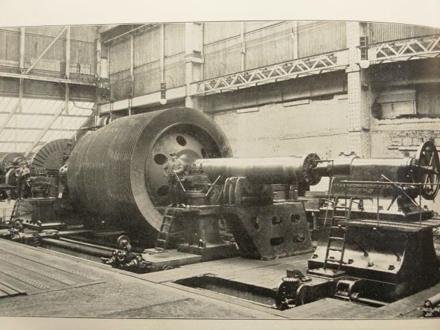
The photo shows one of Mauretania’s LP rotors in at Wallsend Slipway & Engineering, Newcastle-on-Tyne. Note the size of the operators. Just to confuse matters, the lathe was made by Armstrong-Whitworth in Manchester. Incidentally, the town of Wallsend got its name from the fact that it was the Eastern end of the Roman Hadrian’s Wall.
The finished LP rotors weighed 125 tons. Each LP rotor had no less than 50,000 blades. These were fitted in only two weeks, helped by the fact that as far as possible they were pre-assembled in groups before fitting to the rotor.
The following link shows a collection of toffs being taken past some of the turbine casings, borne in cars to minimise the chance of coming into contact with any of the working class heroes.....
Casings
To be fair, the visitors had a lot to see, as they were also taken to the shipyard and driven through some of the recumbent funnels......
http://www.amber-online.com/gallery/exhibition39/image39-628.html
The cast iron turbine casings were marvels of foundry work. Not only were the casings extensively ribbed, the ribs themselves had flanges (i.e. the ribs were T-shaped in cross section). Plenty of overtime in the core shop, then.
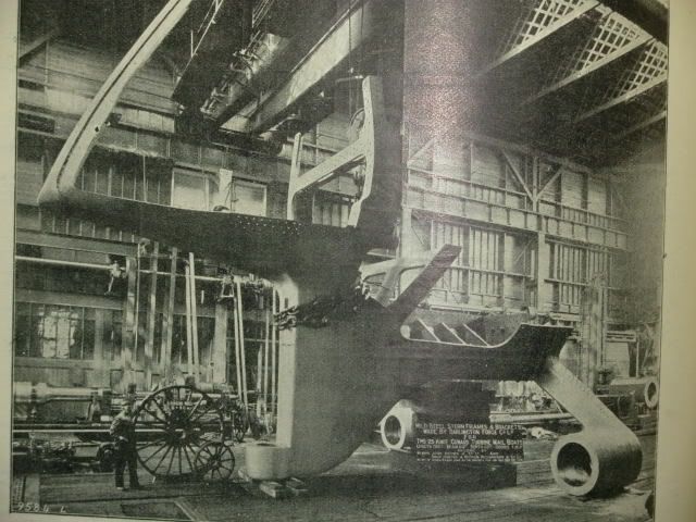
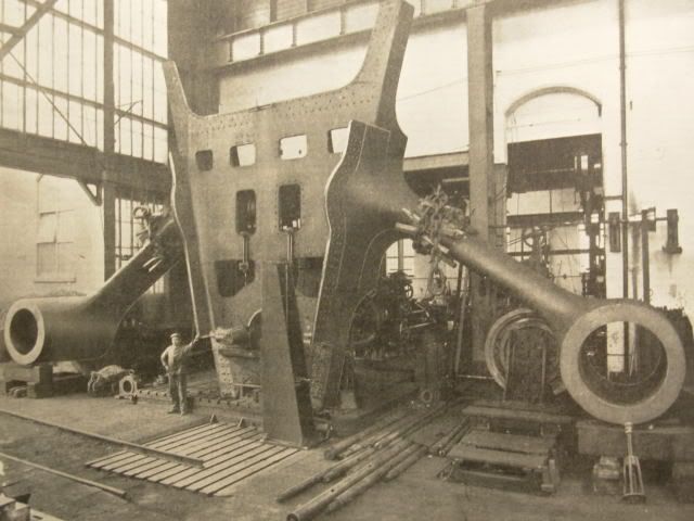
Another foundry feat was the casting of the shapely steel stern frames, by the Darlington Forge Co.:-
The owners, Cunard, showed great confidence in the fairly new fangled technology by opting for turbine propulsion on a big scale.
The turbine rotors comprised a forged shaft on which cast steel wheels were shrunk. Then, shrunk onto the wheels, was a cylinder (the drum or barrel), which was machined to receive thousands of blades.
I’d previously posted a description of how hollow turbine rotor barrels or drums were being made by expanding a hollow forging using squeeze rollers in 1903. For some reason, Lusitania’s rotor drums were forged at John Brown’s in Sheffield in the ‘traditional’ way using a hydraulic press and a mandrel. Quite a feat, at nearly 12 feet diameter and only about 3” thick.
Mauretania’s LP rotor drums must have been even more of a challenge. They were forged with integral flanges and ribs inside the drum. Each finished drum was actually assembled from three separate barrels approx 12 feet diameter and 2 inches thick (about 6 inches thick at the internal ribs and flanges). The three sections were SCREWED together, after heating the female section to give a shrink fit. Buttress threads were adopted. If threads with tapered contact faces had been used, this would have caused unwanted stresses to build up as the hot ‘female’ drum contracted. Finally the internal flanges were bolted together.
Mauretania’s rotor forgings were produced by Armstrong-Whitworth in Manchester using ‘Whitworth’s fluid pressured steel’ (the molten metal in the ingot mould being subjected to enormous hydrostatic pressure with the aim of improving homogenity). By the way, that’s Whitworth as in Joseph Whitworth and Armstrong as in William ‘Hydraulic’ Armstrong (as in Armstrong, Mitchell - cranemakers, shipbuilders, etc of Newcastle).
The photo shows one of Mauretania’s LP rotors in at Wallsend Slipway & Engineering, Newcastle-on-Tyne. Note the size of the operators. Just to confuse matters, the lathe was made by Armstrong-Whitworth in Manchester. Incidentally, the town of Wallsend got its name from the fact that it was the Eastern end of the Roman Hadrian’s Wall.
The finished LP rotors weighed 125 tons. Each LP rotor had no less than 50,000 blades. These were fitted in only two weeks, helped by the fact that as far as possible they were pre-assembled in groups before fitting to the rotor.
The following link shows a collection of toffs being taken past some of the turbine casings, borne in cars to minimise the chance of coming into contact with any of the working class heroes.....
Casings
To be fair, the visitors had a lot to see, as they were also taken to the shipyard and driven through some of the recumbent funnels......
http://www.amber-online.com/gallery/exhibition39/image39-628.html
The cast iron turbine casings were marvels of foundry work. Not only were the casings extensively ribbed, the ribs themselves had flanges (i.e. the ribs were T-shaped in cross section). Plenty of overtime in the core shop, then.
Another foundry feat was the casting of the shapely steel stern frames, by the Darlington Forge Co.:-
 activities included astronomical telescopes. Grubb-Parsons stayed in the business for many years, and I saw one of their mirror grinding machines when I visited Parsons’ works in the 1990s. Probably the one in the first photo here:-